Electrical control system for shoe sole cleaning machine
An electric control system and sole cleaning machine technology, applied in cleaning equipment, boots and shoes cleaning, household cleaning devices, etc., can solve the problems of high energy consumption, high dependence, and large damage of electrical components, and achieve a solution The effect of matching water volume and displacement, low dependence, and high practicability
- Summary
- Abstract
- Description
- Claims
- Application Information
AI Technical Summary
Problems solved by technology
Method used
Image


Examples
Embodiment 1
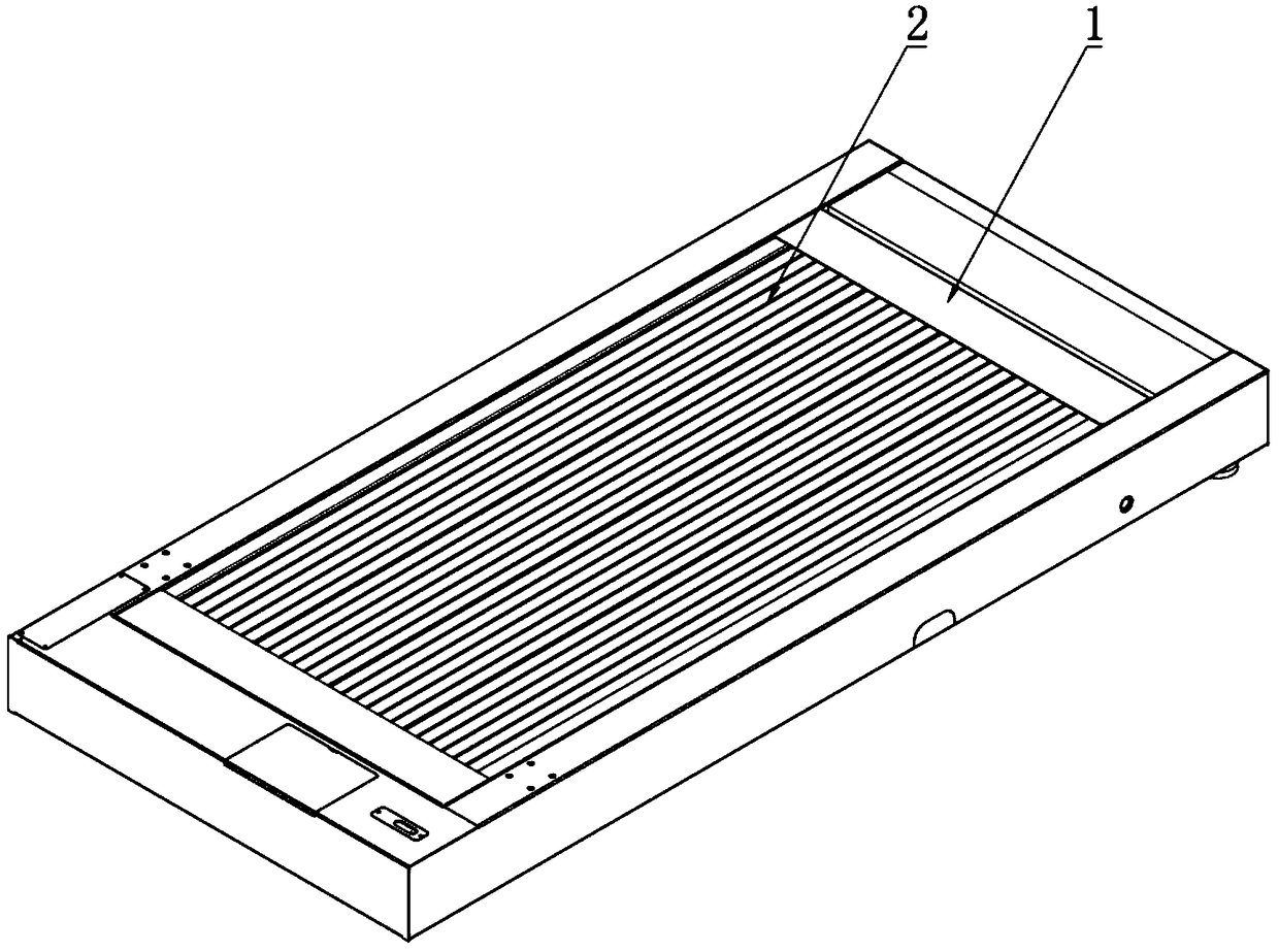
[0042] Such as figure 1 As shown, the electrical control system of a shoe sole cleaning machine according to the present invention includes an input part, a controller and an execution part. The input part, the controller and the execution part are connected through wired electric transmission to form a complete electric control system. Wherein, the input part converts the measured variable into at least one instruction, and the instruction is a command for communicating with the controller and controlling the execution part, so as to achieve the purpose of intelligently controlling the shoe sole cleaning machine.
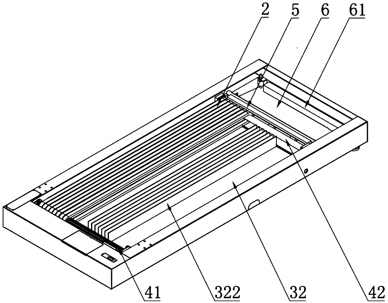
[0043] Wherein, the execution part is each functional device arranged in the body, and the specific electrical components and mechanisms of the functional device are as follows: Figure 2 to Figure 5 As shown, a crawler-type shoe sole cleaning machine according to the present invention includes several crawlers 2 built in the body 1, a drive mechanism 4 connected ...
Embodiment 2
[0062] The electrical control system of a shoe sole cleaning machine described in Embodiment 2 is similar to the system composition of Embodiment 1, the difference is that the water level detection assembly includes dual water level sensors and a limit water level sensor, which are respectively used It is used to detect the high water level, low water level and limit water level in the drainage device.
[0063] Specifically, the dual water level sensors are water level photoelectric sensors installed on the side wall of the sewage tank for detecting the high water level and low water level in the sewage tank and generating corresponding instructions. The limit water level sensor is an electronic float switch installed in the sewage tank to detect the limit water level and generate corresponding instructions.
[0064] In the electrical control system of Embodiment 2, preferably, the auxiliary detection component of the input part includes a human body detection component. Spec...
Embodiment 3
[0070] Such as Image 6 As shown, the crawler-type shoe sole cleaning machine described in the present embodiment 3 is similar in structure to the embodiment 2, the difference is that the sewage tank 6 is an inclined tank body, and the inclination of the sewage from the sewage tank 6 The high position flows into the bottom of the sewage tank 6.
[0071] Specifically, the sewage tank 6 is a tank box surrounded by an inclined bottom plate and three side plates on the bottom plate, forming an inclined tank body that is easy to collect sewage. Wherein the higher end of the bottom plate is the inclined high position, which is connected to the straight plate 32 of the self-cleaning plate 3 . The bottom plate has a drainage effect on the sewage, and the sewage on the scraper 321 is introduced into the sewage tank 6 .
[0072] The double water level sensor is installed on the bottom side wall and the top side wall of the sewage tank 6, and is used to detect the high water level and ...
PUM
 Abstract
Description
Claims
Application Information
 - Generate Ideas
- Intellectual Property
- Life Sciences
- Materials
- Tech Scout
- Unparalleled Data Quality
- Higher Quality Content
- 60% Fewer Hallucinations
Browse by: Latest US Patents, China's latest patents, Technical Efficacy Thesaurus, Application Domain, Technology Topic, Popular Technical Reports.
© 2025 PatSnap. All rights reserved.Legal|Privacy policy|Modern Slavery Act Transparency Statement|Sitemap|About US| Contact US: help@patsnap.com