
Dynamic and static wind ring

A static wind and dynamic wind technology, applied in the wind ring, static wind ring, and dynamic fields, can solve the problems of affecting the pulverization performance of medium-speed mills, poor ability to return coarse powder, and large air leakage rate, so as to improve the powder return ability , Improve the conveying capacity and powder return ability, and reduce the effect of air leakage rate

Pending Publication Date: 2018-12-07
SHANGHAI YIFENG ELECTRICAL & MECHANICAL TECH DEV
View PDF7 Cites 0 Cited by
  • Summary
  • Abstract
  • Description
  • Claims
  • Application Information

AI Technical Summary

Problems solved by technology

Due to the limitations of its structure, there are defects such as large air leakage rate and poor ability to return coarse powder to the grinding table. These defects seriously affect the pulverizing performance of medium-speed mills, and will cause problems such as low output, high power consumption, and serious wear.

Method used


Image

  • Dynamic and static wind ring
  • Dynamic and static wind ring
  • Dynamic and static wind ring

Examples


Embodiment Construction

[0027] The following will clearly and completely describe the technical solutions in the embodiments of the present invention with reference to the accompanying drawings in the embodiments of the present invention. Obviously, the described embodiments are only some, not all, embodiments of the present invention. Based on the embodiments of the present invention, all other embodiments obtained by persons of ordinary skill in the art without making creative efforts belong to the protection scope of the present invention.

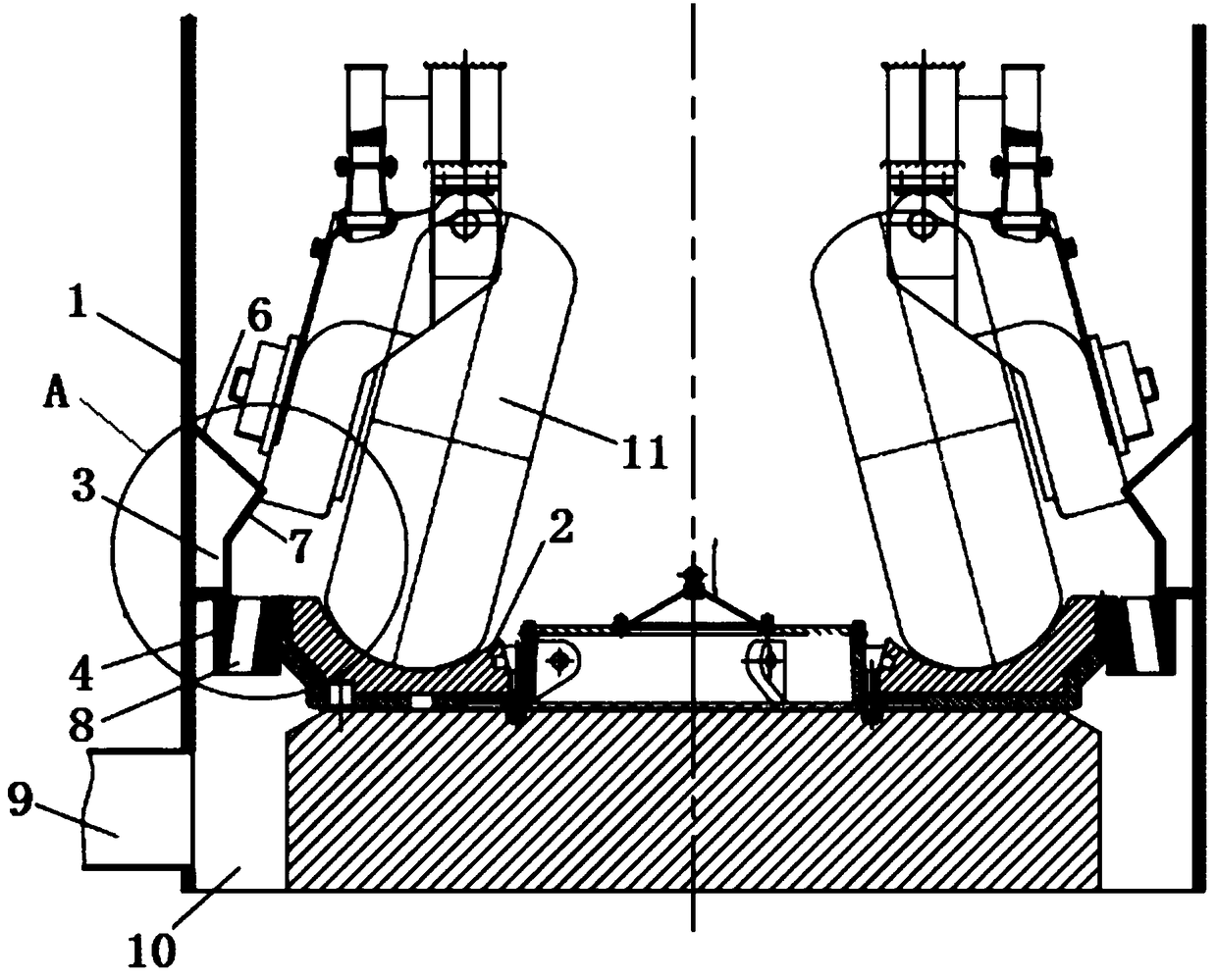
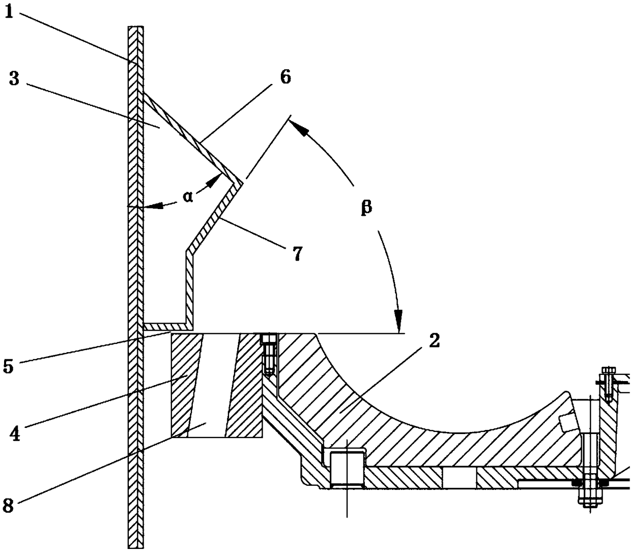
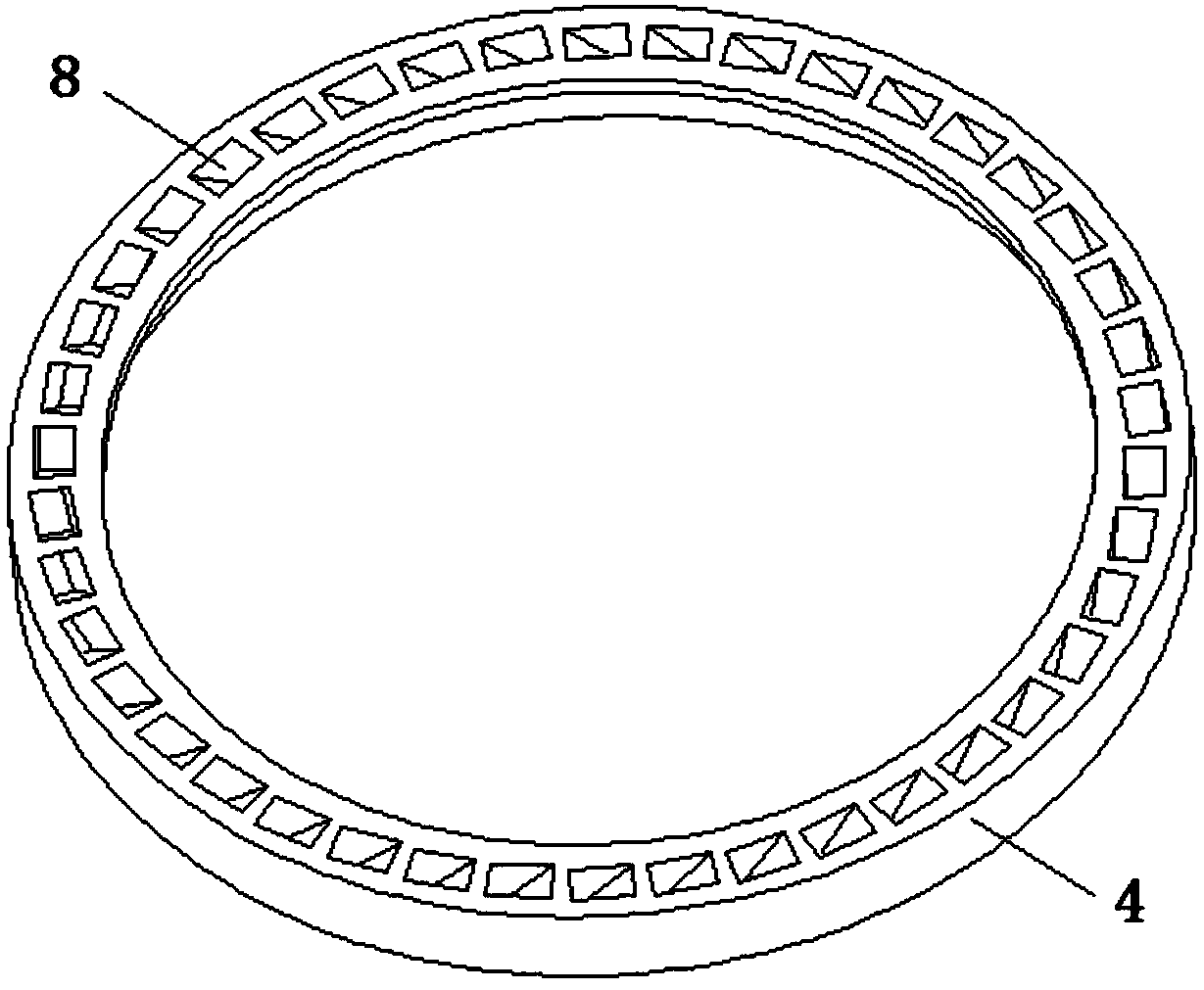
[0028] The embodiment of the invention discloses a dynamic and static wind ring, and the gap between the dynamic and static wind rings is set as an annular plane gap, which reduces the air leakage rate and improves the conveying capacity of the load wind and the ability to return powder; the static wind ring is set The upper and lower guide surfaces further improve the powder returning ability.

[0029] Please refer to the attached Figure 1-5 , the present i...


PUM


Abstract

The invention discloses a dynamic and static wind ring; one side of the dynamic and static wind ring is fixedly connected with a cylinder body, the other side of the dynamic and static wind ring is fixedly connected with a grinding disc; the dynamic and static wind ring includes a static wind ring and a dynamic wind ring; the static wind ring is fixed on the cylinder body, the dynamic wind ring isarranged on the grinding disc, and an annular plane gap is formed between the static wind ring and the dynamic wind ring; the static wind ring includes an upper guiding surface and a lower guiding surface connected with the upper guiding surface. Compared with traditional dynamic and static wind rings, the dynamic and static wind ring disclosed by the invention greatly improves the conveying capacity and the powder returning capacity, thereby improving the overall powder preparation performance of a medium-speed mill.

Description

technical field [0001] The invention relates to an air ring, more specifically relates to a dynamic and static air ring, and belongs to the technical field of mechanical manufacturing. Background technique [0002] The dynamic and static air rings are located between the inner grinding disc and the barrel of the medium-speed mill, and are the main channel for the load wind to enter the medium-speed mill. The function of conveying fine powder and returning coarse powder to the grinding disc. In addition, the dynamic and static air rings also have the function of filtering, and the foreign matter that cannot be ground into the medium-speed mill is removed from the medium-speed mill, and the qualified materials are blocked by the air ring and will not be mis-discharged. [0003] The traditional dynamic and static air ring structure, the static air ring is welded on the cylinder, the dynamic air ring is fixed on the millstone, and rotates with the millstone, the load wind enter...

Claims


Application Information

Patent Timeline
Patent Type & Authority Applications(China)
IPC IPC(8): B02C23/34B02C15/00
CPCB02C15/00B02C23/34B02C2015/002
Inventor 何锋发陈刚李大正杨博程华孙佳麒
Owner SHANGHAI YIFENG ELECTRICAL & MECHANICAL TECH DEV
Learn More