Manufacturing method of liquid injector head

A technology of a liquid jet head and a production method, which is applied in the field of production of liquid jet heads, can solve the problems of incapable of satisfying play people, single water gun, etc., and achieves the effects of simple structure and convenient operation.

Inactive Publication Date: 2018-12-07
余名宪
View PDF0 Cites 2 Cited by
  • Summary
  • Abstract
  • Description
  • Claims
  • Application Information

AI Technical Summary

Problems solved by technology

[0002] There are various water guns on the market at present, but the existing water guns are relatively single, generally only have one water storage tank, so water needs to be added after spraying for a short time, and a single clear water liquid can not satisfy the interest of the players. Therefore, there is an urgent need to design a water tank that integrates multiple water storage tanks, which can store liquids of different colors, and can be easily switched to satisfy the interest of gamers.

Method used


Image

  • Manufacturing method of liquid injector head
  • Manufacturing method of liquid injector head
  • Manufacturing method of liquid injector head

Examples


Embodiment Construction

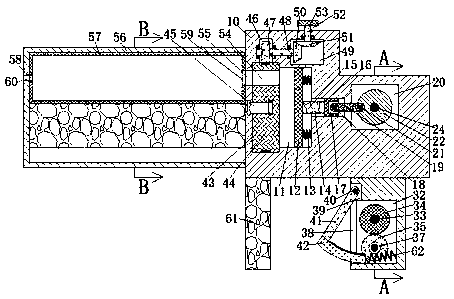
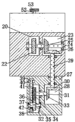
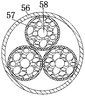
[0014] Combine below Figure 1-3 The present invention will be described in detail.

[0015] refer to Figure 1-3 , a manufacturing method of a liquid ejection head according to an embodiment of the present invention, comprising a device body 10, an injection device disposed in the device body 10, and a switching device disposed in the device body 10, the switching device It includes a first working chamber 11 arranged in the main body 10 of the device, and a sliding plate 12 is connected to the first working chamber 11 by sliding fit. The first spring 13 is fixedly connected to the right end of the chamber 11, the right end wall of the first working chamber 11 is communicated with a connecting rod chamber 14, and the right end of the slide plate 12 is fixed with a first connecting rod 15 extending to the right. , the right end of the first connecting rod 15 is fixed with a slider 16 that is slidably connected to the connecting rod chamber 14, and the slider 16 is provided w...


PUM


Abstract

The invention discloses a manufacturing method of a liquid injector head. The liquid injector head comprises a device body, an injection device arranged in the device body and a switching device arranged in the device body. The switching device comprises a first working cavity formed in the device body. A slide plate is connected into the first working cavity in a sliding fit mode. First springs are fixedly arranged on the right end surface of the slide plate and symmetric up and down, and the right ends of the first springs are fixedly connected with the right side end surface of the first working cavity. The right side end wall of the first working cavity communicates with a connecting rod cavity. A first connecting rod extending rightwards is fixedly arranged on the right end surface ofthe slide plate. A slide block connected with the connecting rod cavity in a sliding fit mode is fixedly arranged at the right end of the first connecting rod. An internal connecting groove with a rightward opening is formed in the slide block. First fixing shafts are fixedly arranged on the front and rear side end walls of the internal connecting groove correspondingly. According to the device,a plurality of water tanks are integrated, an increase of the water storage amount can prolong the injection time of a water gun, liquid in different colors can be injected, and the experience feelingof a player is improved.

Description

technical field [0001] The invention relates to the field of toys, in particular to a method for manufacturing a liquid ejection head. Background technique [0002] There are various water guns on the market at present, but the existing water guns are relatively single, generally only have one water storage tank, so water needs to be added after spraying for a short time, and a single clear water liquid can not satisfy the interest of the players. Therefore be badly in need of designing a kind of a plurality of water storage tanks to be integrated, can deposit liquid of different colors, and switch convenient water gun, satisfy the interest of the player to game. Contents of the invention [0003] The object of the present invention is to provide a method for manufacturing a liquid ejection head, which is used to overcome the above-mentioned defects in the prior art. [0004] A method of manufacturing a liquid jet head according to the present invention, comprising a devi...

Claims


Application Information

Patent Timeline
Patent Type & Authority Applications(China)
IPC IPC(8): B05B9/03B05B12/14
CPCB05B9/03B05B12/149
Inventor 余名宪
Owner 余名宪
Why Eureka
Try Eureka