Atmospheric pressure plasma jet device

A plasma and jet device technology, applied in the field of plasma, can solve problems such as difficulty, and achieve the effects of high application efficiency, high discharge efficiency and compact structure

Active Publication Date: 2020-03-24
武汉海思普莱生命科技有限公司
View PDF14 Cites 1 Cited by
  • Summary
  • Abstract
  • Description
  • Claims
  • Application Information

AI Technical Summary

Problems solved by technology

Inert gas jets at atmospheric pressure are easy to achieve, while non-inert gas jets at atmospheric pressure are more difficult

Method used


Image

  • Atmospheric pressure plasma jet device
  • Atmospheric pressure plasma jet device
  • Atmospheric pressure plasma jet device

Examples


Embodiment 1

[0057] In the embodiment of the present invention, air is used as the working gas; the rotating electrode is used as the high voltage electrode, and the fixed electrode is used as the ground electrode; the speed of the motor is selected to be 5000r / min; the coupling is made of polytetrafluoroethylene; the transmission connecting rod is made of alumina ceramics Material; the brush is made of graphite; the fixing device of the brush is made of polytetrafluoroethylene; the shaft is made of stainless steel; the high-voltage wire is made of a high-voltage wire with a withstand voltage of 20kV; shaped, integrally formed with the shell of the plasma generator; the rotating electrode is in the shape of a four-pointed star, and its material is stainless steel; the panel where the nozzle is located is made of alumina ceramic sheet; the nozzle is rectangular, obtained by cutting on the alumina ceramic panel; the fixed electrode is made of metal , the material is stainless steel; the base ...

Embodiment 2

[0067] as attached Image 6As shown, in the embodiment of the present invention, the fixed electrodes are set to be arranged on both sides of the nozzle. The nozzle is rectangular, 1 cm long and 2 mm wide. breath. Air is used as the discharge gas, the fixed electrode is used as the high voltage electrode, and the rotating electrode is used as the ground electrode.

Embodiment 3

[0071] as attached Figure 8 As shown, in the embodiment of the present invention, the telescopic motor controls the vertically telescoping electrode 4.8 to stretch up and down through the insulating transmission device, and the high-voltage power supply supplies power to the telescopic electrode 4.8 through the conductive transmission device. In the initial state, the telescopic electrode 4.8 moves downward and approaches the fixed electrode 4.1. When the distance decreases to the maximum breakdown distance, the discharge starts to generate plasma flow. The sensor 4.7 detects the discharge and sends a signal to the telescopic motor to make it pull The telescopic electrode 4.8 is far away from the fixed electrode 4.1; as the distance becomes longer, the plasma flow will be elongated, and the discharge will gradually stop at the same time. After the sensor 4.7 detects that the discharge stops, it will send a signal to the telescopic motor to let it pull the telescopic electrode ...


PUM


Abstract

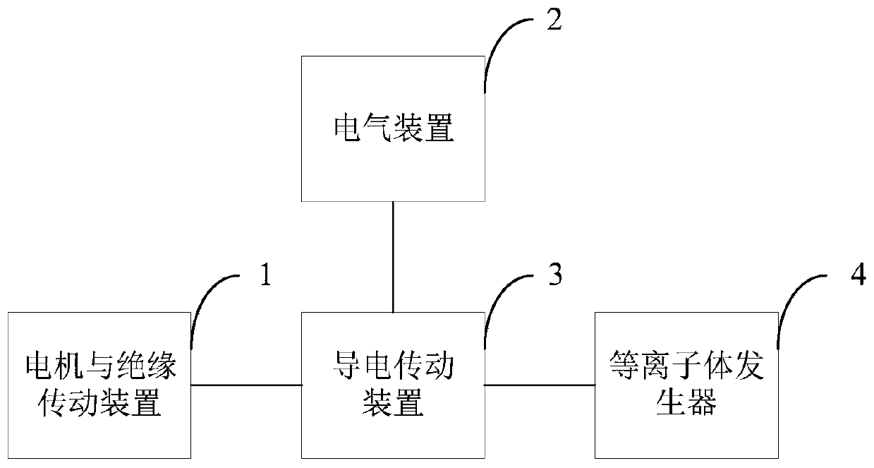
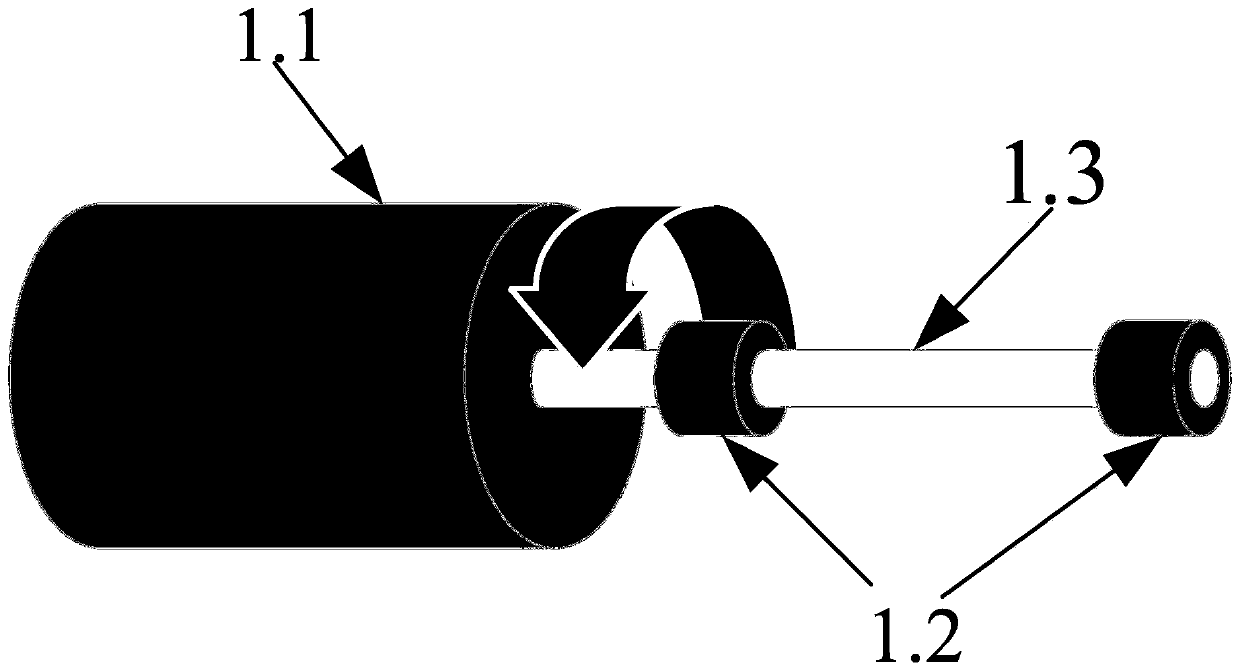
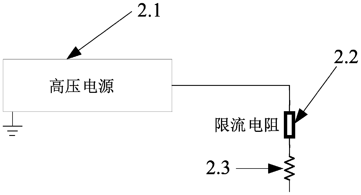
The invention discloses an atmospheric pressure plasma jet device. The device comprises a motor and insulation transmission device, an electrical device, a conductive transmission device and a plasmagenerator, the motor and insulation transmission device comprises a motor and an insulation transmission device, and the electrical device is used for providing high voltage, adjusting current, adjusting plasma temperature, controlling impact current and stabilizing discharge; the conductive transmission device is used for guiding high voltage of the electrical device into the plasma generator andguiding torque of the motor and the insulation transmission device into the plasma generator; the plasma generator is used as a discharge chamber, plasmas are generated in the generator, the plasma flow is lengthened after the plasmas are blown out along with airflow, and plasma jet flow with various kinds of gas serving as working gas under the atmospheric pressure condition is formed. The device is adopted to drive the electrode to lengthen the discharge channel, and then the discharge channel is blown out by airflow, so that jet flow of various working gases can be realized.

Description

technical field [0001] The invention belongs to the field of plasma technology, and more specifically relates to an atmospheric pressure plasma jet device. Background technique [0002] Plasma is a collection of particles composed of electrons, ions, and neutral particles, which is electrically neutral to the outside as a whole. Plasma can be divided into high-temperature plasma and low-temperature plasma. High-temperature plasma is produced by fusion, and low-temperature plasma is usually produced by electric field ionized gas. Because low-temperature plasma has a lower gas temperature, it has a wide range of application prospects. [0003] Plasma jet is an important application form of plasma, and has excellent application prospects in the fields of material modification, surface treatment, plasma chemistry and plasma medical treatment. [0004] At present, the gas generated by the plasma jet is mainly a rare gas, which relies on the gas cylinder to store the working gas...

Claims


Application Information

Patent Timeline
Patent Type & Authority Applications(China)
IPC IPC(8): H05H1/00H05H1/24H05H1/26H05H1/28
CPCH05H1/00H05H1/24H05H1/26H05H1/28
Inventor 卢新培李志宇刘嘉林聂兰兰
Owner 武汉海思普莱生命科技有限公司
Why Eureka
Try Eureka