Mechanically-controlled-type automatic discharging manipulator

A technology of automatic cutting and mechanical control, applied in the field of manipulators, can solve the problems of easy damage of electronic components, affecting production efficiency, time-consuming and labor-intensive testing of electronic components and programs

Pending Publication Date: 2018-12-07
ANHUI UNIV OF SCI & TECH
View PDF0 Cites 9 Cited by
  • Summary
  • Abstract
  • Description
  • Claims
  • Application Information

AI Technical Summary

Problems solved by technology

[0003] In order to ensure that the manipulator can pick up and place parts normally, many sensors will be installed to judge the position of the manipulator, and the computer program will be used to receive data to control the manipulator. This method requires more electronic components. Under working conditions, various electronic components are relatively easy to damage. Once a certain component or computer program fails, the entire processing line needs to be stopped, seriously affecting production efficiency, and the detection of electronic components and programs is very time-consuming and laborious.

Method used


Image

  • Mechanically-controlled-type automatic discharging manipulator
  • Mechanically-controlled-type automatic discharging manipulator
  • Mechanically-controlled-type automatic discharging manipulator

Examples


Embodiment approach

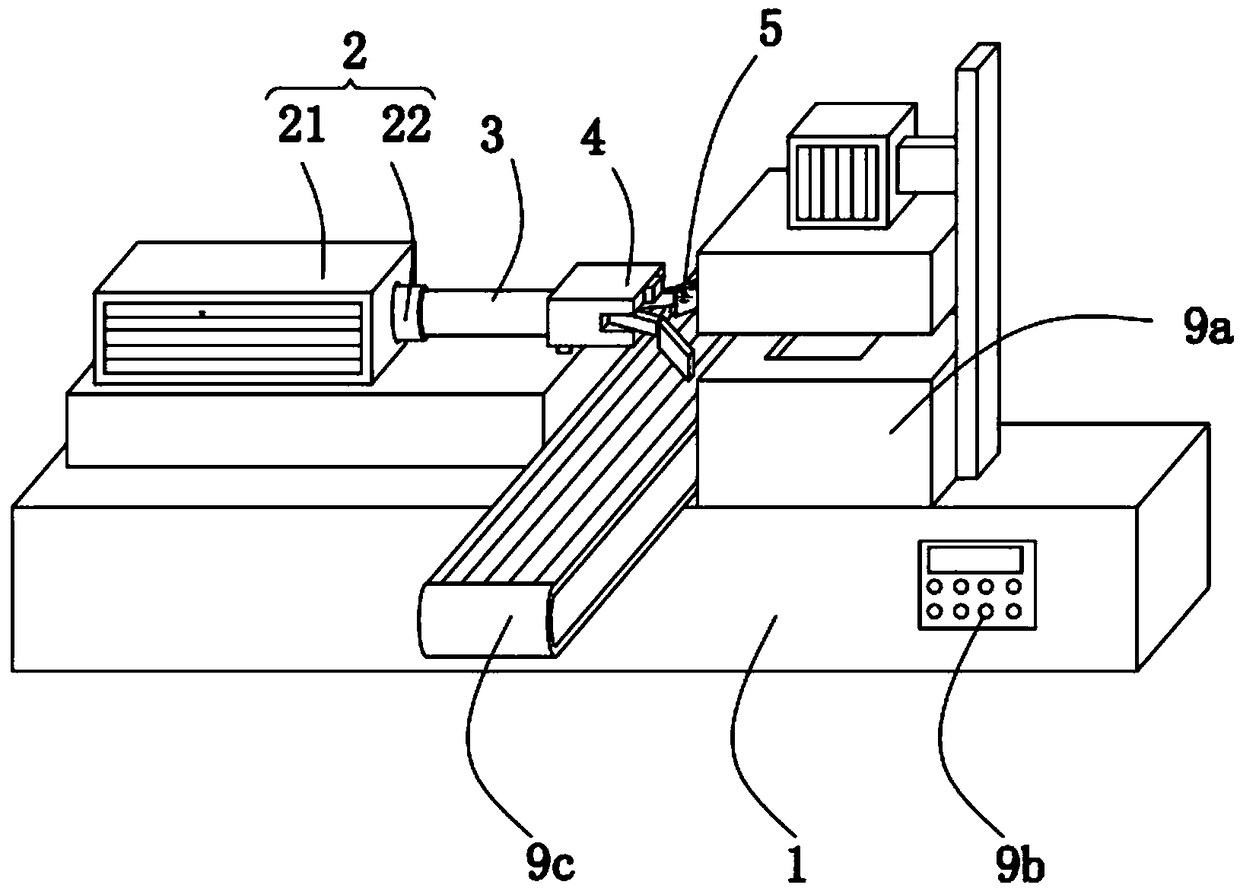
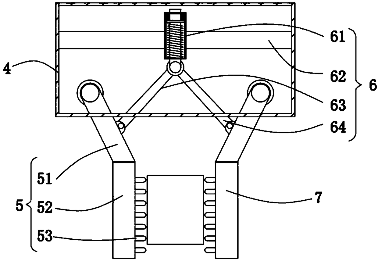
[0029] Implementation method: In the initial state, the pneumatic rod 22 is put into the cylinder 21, the push switch 8 is fixed on the unloading area 312 at the end of the movable rod 3, and the clamping mechanism is located on the top of the conveyor belt 6; when the injection molding of the workpiece is completed, it needs to be picked up At this time, the cylinder 21 drives the pneumatic rod 22 to move outward, and then the pneumatic rod 22 pushes the movable rod 3 to move, the first clamping mechanism 5 and the second clamping mechanism 7 approach the mold, and the switch moves along the blanking area 312, the moving area 311 slides, when the switch moves to the bottom of the first extrusion block 32, the clamping mechanism moves to the outside of the workpiece, and the first extrusion block 32 squeezes the switch to make the switch conduct electricity;

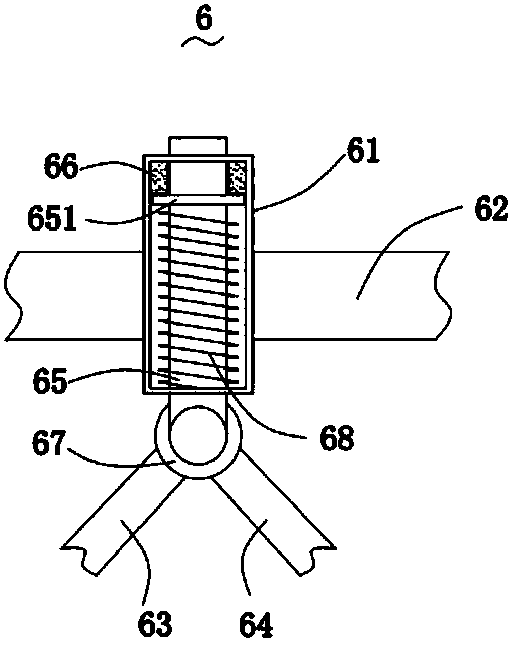
[0030] The first electromagnet 66 is energized, the adsorption pressure plate 651 slides upwards and elongates the seco...


PUM


Abstract

The invention relates to the field of manipulators, in particular to a safety auxiliary device used for a non-motor vehicle. The invention discloses a mechanically-controlled-type automatic discharging manipulator which comprises a base, a pneumatic mechanism, a movable rod, a box body, a first clamping mechanism, an opening and closing mechanism, a pressing-type switch, an adjusting and controlling mechanism, a machining mould, a power box and a conveyer belt. According to the mechanically-controlled-type automatic discharging manipulator, the clamping manipulator is pushed by the pneumatic mechanism; the pressing-type switch can move along the bottom surface of the movable rod; when the clamping mechanism moves to two sides of a workpiece, a first pressing block presses down the switch,so that the clamping mechanism can clamp the workpiece, and automatic clamping is realized; when the switch is electrified, a second pressing block is flush with the first pressing block, so that theclamping mechanism can maintain a clamping state when a pneumatic rod is at a retrieving state; when the workpiece moves to the top of the conveyer belt, the pressing-type switch is reset and powered-off, so that the opening and closing mechanism drives the clamping mechanism to open; the workpiece falls on the conveyer belt, so that discharging and conveying are realized; and besides, the adjusting and controlling mechanism moves upwards to be reset, so that circular work is realized.

Description

technical field [0001] The invention relates to the field of manipulators, in particular to a mechanically controlled automatic unloading manipulator. Background technique [0002] A manipulator is an automatic operating device that can imitate certain actions of the human hand and arm to grab, carry objects or operate tools according to a fixed program; in the mold processing production line, a manipulator will be installed next to the mold to remove high temperature state of the workpiece, to achieve blanking. [0003] In order to ensure that the manipulator can pick up and place parts normally, many sensors will be installed to judge the position of the manipulator, and the computer program will be used to receive data to control the manipulator. This method requires more electronic components. Under working conditions, various electronic components are relatively easy to damage. Once a certain component or computer program fails, the entire processing line needs to be s...

Claims


Application Information

Patent Timeline
Patent Type & Authority Applications(China)
IPC IPC(8): B25J15/00B25J18/02
CPCB25J15/00B25J15/0095B25J18/025
Inventor 史先春沈梅郭煜陈业富储伟建刘雷
Owner ANHUI UNIV OF SCI & TECH
Why Eureka
Try Eureka