
Pipe cutting device

A technology of pipe cutting equipment and cutting mechanism, which is applied in the field of pipe processing, and can solve problems such as uneven incision at the cutting place and poor fixing of pipe materials, and achieve the effect of solving uneven incision and wide applicability

Active Publication Date: 2018-12-07
宁波隆锐机械制造有限公司
View PDF4 Cites 18 Cited by
  • Summary
  • Abstract
  • Description
  • Claims
  • Application Information

AI Technical Summary

Problems solved by technology

[0003] The present invention intends to provide a pipe cutting equipment to solve the problem in the prior art that the pipes are not fixed properly and the cuts at the cutting place are uneven

Method used


Image

  • Pipe cutting device
  • Pipe cutting device

Examples


Embodiment Construction

[0014] The present invention will be described in further detail below by means of specific embodiments:

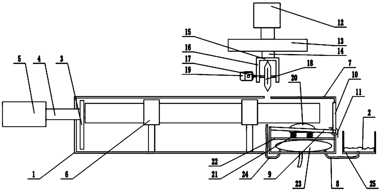
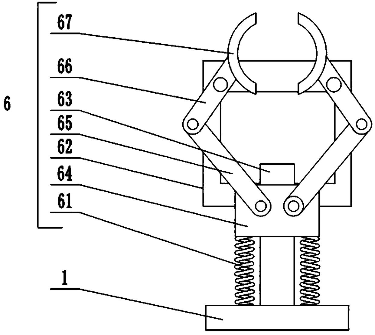
[0015] The reference signs in the drawings of the description include: sleeve 1, air cushion 2, push plate 3, push rod 4, cylinder 5, clamping mechanism 6, first spring 61, frame body 62, chute 63, push block 64, First connecting rod 65, second connecting rod 66, clamping member 67, connecting sleeve 7, second air outlet pipe 8, inclined rod 9, rotating plate 10, torsion spring 11, hydraulic cylinder 12, cutting connecting plate 13, cutting slide Block 14, cutting main board 15, long plate 16, rotating shaft 17, cutting blade 18, motor 19, mast 20, second spring 21, pressing plate 22, elastic air bag 23, the first air outlet pipe 24, collection frame 25.

[0016] The embodiment is basically as attached figure 1 , 2 Shown: a pipe cutting equipment, including a frame, a sleeve 1, a cutting mechanism and a connecting sleeve 7 are installed on the frame, the sleeve 1 is pro...


PUM


Abstract

The patent relates to the technical field of pipe machining, in particular to a pipe cutting device. The pipe cutting device comprises a machine frame, a sleeve, a cutting mechanism and a connecting sleeve are arranged on the machine frame, a first opening is formed in the sleeve, a push plate is slidably connected in the sleeve, the push plate is connected with a push rod, the push rod penetratesthrough the side wall of the sleeve, and an air cylinder is connected to one end, extending out of the sleeve, of the push rod; a plurality of clamping mechanisms are arranged in the sleeve; the connecting sleeve is provided with a third opening, and the first opening and the third opening are oppositely arranged; and an inclined rod is fixedly connected in the connecting sleeve, a discharging opening is formed in the connecting sleeve, and a rotating plate is hinged to the discharging opening. According to the pipe cutting device, pipes can be clamped and fixed through the clamping mechanisms, the pipes can be cut through the cutting mechanism, and the pipe cutting device can adapt to the pipes with different diameters through distance changing between clamping pieces.

Description

technical field [0001] The invention relates to the technical field of pipe processing, in particular to a pipe cutting device. Background technique [0002] In the field of mechanical processing technology, the cutting of pipes is often involved. At present, the commonly used cutting form is manual cutting, that is, first measure the length of the required pipe, and then use a cutting machine to cut. When cutting, one side of the cutting place needs to be cut manually. Press and fix it, and then use the cutting machine to cut the designated cutting place. During the operation, because the manual pressing force is not stable, the pipe cannot be fixed well, which will make the incision at the cutting place uneven, and the effect is not ideal. Contents of the invention [0003] The present invention intends to provide a pipe material cutting device to solve the problem in the prior art that the pipe material is not fixed properly and the cuts at the cutting place are uneven....

Claims


Application Information

Patent Timeline
IPC IPC(8): B26D7/04B26D1/157B26D3/16
CPCB26D1/157B26D3/16B26D7/04
Inventor 金小光
Owner 宁波隆锐机械制造有限公司
Learn More