Electronic control stapler

An electronic control and stapler technology, which is applied in binding and other directions, can solve the problems of less number of staples in binding, slow binding efficiency, difficult control of the number of staples, etc., and achieve the effect of simple structure, good binding effect and convenient operation

Inactive Publication Date: 2018-12-07
绍兴翌利电器有限公司
View PDF0 Cites 0 Cited by
  • Summary
  • Abstract
  • Description
  • Claims
  • Application Information

AI Technical Summary

Problems solved by technology

[0002] With the development of science and the progress of society, the country has been promoting the development of advanced technology. Among them, there has always been a relatively difficult technical problem in the field of stapler technology. The general binding machine has a slow binding efficiency and a large number of staples. less, the number of nails is difficult to control, and cannot meet the necessary requirements. The device of the present invention solves this problem

Method used


Image

  • Electronic control stapler
  • Electronic control stapler
  • Electronic control stapler

Examples


Embodiment Construction

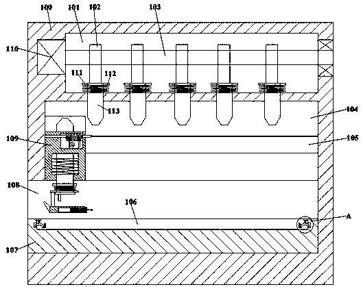
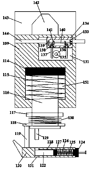
[0016] Such as figure 1 , figure 2 and image 3 As shown, the electronically controlled stapler of the present invention includes a body 100 and a transposition chamber 104 arranged in the body 100, the bottom of the transposition chamber 104 communicates with a filling chamber 108 with an opening left, so The top of the transposition cavity 104 is provided with a first cavity 101, and the front and rear inner walls of the transposition cavity 104 communicate with each other and are provided with symmetrical tooth grooves 105, and the drive carrier 109 is slidably connected to the transposition cavity 104. The drive carrier 109 is provided with a second cavity 131, and the second cavity 131 is rotatably connected with a first rotating shaft 135 extending front and rear, and the front and rear ends of the first rotating shaft 135 pass through the front and rear end surfaces of the drive carrier 109. And be provided with the gear meshingly connected with described tooth groov...


PUM


Abstract

The invention discloses an electronic control stapler. The electronic control stapler comprises a machine body and a position changing cavity formed in the machine body. The bottom of the position changing cavity is connected with a leftward-opening filling cavity. A first cavity is formed in the top of the position changing cavity. Symmetric tooth grooves are connected with the front inner wall and the rear inner wall of the position changing cavity. A drive carrier is connected in the position changing cavity with a sliding fit. A second cavity is formed in the drive carrier. A front-back-extending first rotation shaft is connected in the second cavity with a running fit. The front tail end and the rear tail end of the first rotation shaft penetrate through the front end face and the rear end face of the drive carrier and are provided with gears which are in meshing connection with the tooth grooves. The first rotation shaft is provided with a worm gear located in the second cavity,a first guiding sliding block is connected in the second cavity with a running fit and internally provided with a third cavity, and the bottom wall of the third cavity is internally connected with left-right-symmetry and up-down-extending worms with a running fit.

Description

technical field [0001] The invention relates to the technical field of staplers, in particular to an electronically controlled stapler. Background technique [0002] With the development of science and the progress of society, the country has been promoting the development of advanced technology. Among them, there has always been a relatively difficult technical problem in the field of stapler technology. The general binding machine has a slow binding efficiency and a large number of staples. Less, the number of nails is difficult to control and cannot meet the necessary requirements. The device of the present invention solves this problem. Contents of the invention [0003] The technical problem to be solved by the present invention is to provide an electronically controlled stapler, which can solve the above-mentioned problems in the prior art. [0004] The present invention is achieved through the following technical solutions: the electronically controlled stapler of ...

Claims


Application Information

Patent Timeline
Patent Type & Authority Applications(China)
IPC IPC(8): B42B5/08
CPCB42B5/08
Inventor 金梦佳
Owner 绍兴翌利电器有限公司
Why Eureka
Try Eureka