
Variable-diameter positioning pin structure and multiple-vehicle-type rail trolley

A technology of positioning pins and trolleys, applied to conveyors, mechanical conveyors, transportation and packaging, etc., can solve the problems of cost increase, inconvenient storage, waste of resources, etc., and achieve the effects of saving costs, facilitating storage, and convenient operation

Pending Publication Date: 2018-12-07
烟台宇信科技有限公司
View PDF0 Cites 3 Cited by
  • Summary
  • Abstract
  • Description
  • Claims
  • Application Information

AI Technical Summary

Problems solved by technology

like Figure 14 Shown is the positioning support pin structure of a track trolley in the automatic production line of a single model. The diameter of the positioning support pin is determined according to the positioning hole of the current model and cannot be changed. Therefore, once the positioning support pin of the track trolley is completed, it can only be adapted to one model. , if the model is changed, it is required to re-make positioning support pins of appropriate size, so developing different trolleys for different models wastes resources, increases costs, takes up space, and is inconvenient to store

Method used


Image

  • Variable-diameter positioning pin structure and multiple-vehicle-type rail trolley
  • Variable-diameter positioning pin structure and multiple-vehicle-type rail trolley
  • Variable-diameter positioning pin structure and multiple-vehicle-type rail trolley

Examples


Embodiment Construction

[0057] The principles and features of the present invention are described below in conjunction with examples, which are only used to explain the present invention and are not intended to limit the scope of the present invention.

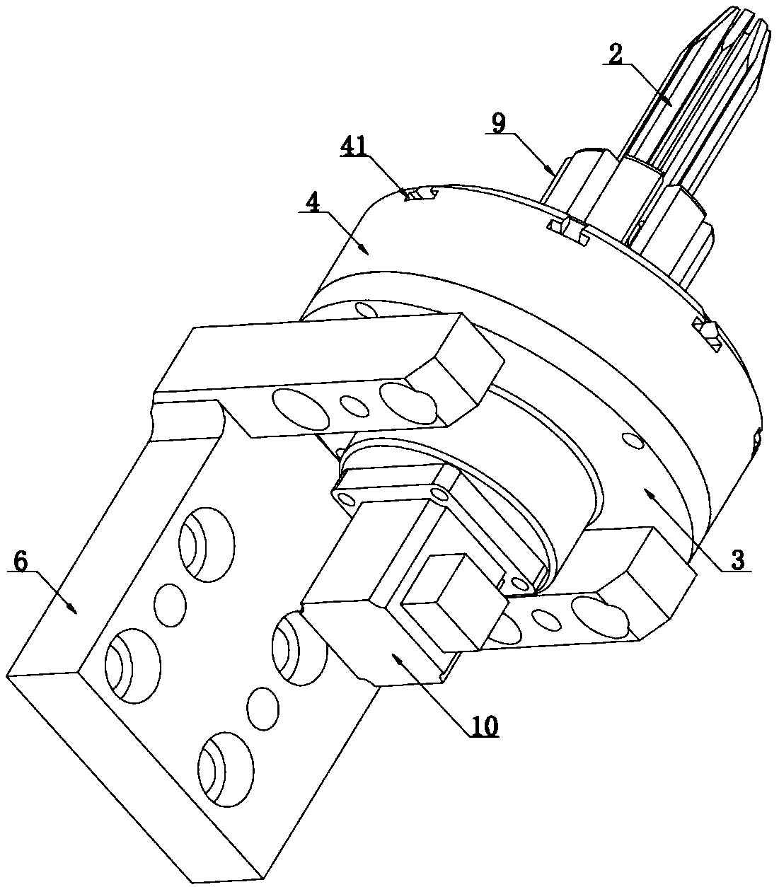
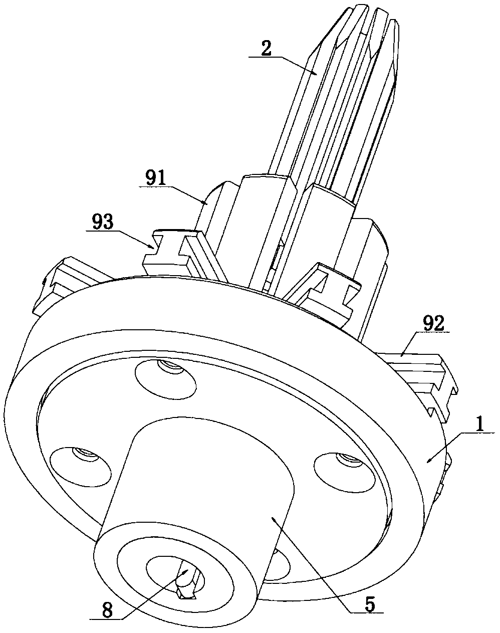
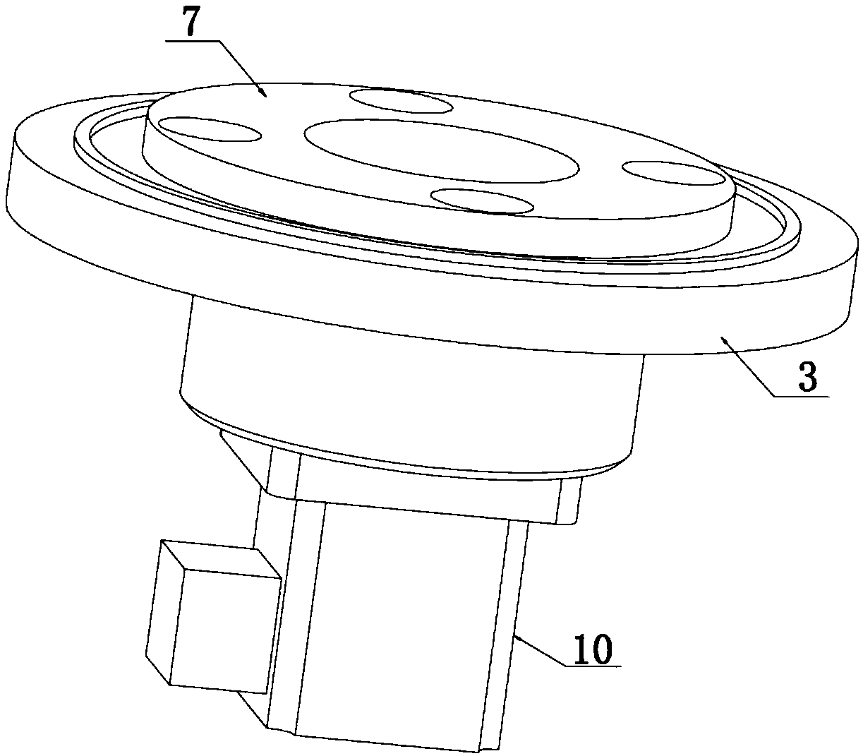
[0058] Such as Figure 1-Figure 9 As shown, a variable diameter positioning pin structure includes a mounting base 3, a turntable 1 arranged on the mounting base, a servo motor 10 for driving the turntable to rotate, a protective cover 4 and a plurality of pin claws 2, and the servo motor is installed On the mounting seat, a shaft hole is provided on the mounting seat, the output shaft of the servo motor passes through the shaft hole to connect with the turntable, the protective cover is sleeved on the outside of the turntable, and The mounting seat is connected, the upper surface of the protective cover is provided with a plurality of radial notches 41, the claws are installed on the claw seat 9, and the claw seats are correspondingly installed in t...


PUM


Abstract

The invention discloses a variable-diameter positioning pin structure and a multiple-vehicle-type rail trolley. The variable-diameter positioning pin structure comprises a mounting seat, a rotating disc, a servo motor, a protective cover and a plurality of pin claws. The servo motor is mounted on the mounting seat, a shaft hole is formed in the mounting seat, and an output shaft of the servo motorpenetrates through the shaft hole to be connected with the rotating disc. The protective cover is mounted on the outer side of the rotating disc in a sleeving mode and connected with the mounting seat. A plurality of radial notches are formed in the upper surface of the protective cover. The pin claws are mounted on pin claw seats, and the pin claw seats are mounted in the radial notches correspondingly. A rotating disc thread is arranged on the upper surface of the rotating disc. Pin seat threads are arranged at the bottoms of the pin claw seats. The multiple pin claws are evenly distributedto form a positioning column in a surrounding mode. The servo motor makes action to adjust the outer diameter of the positioning column. According to the variable-diameter positioning pin structure and the multiple-vehicle-type rail trolley, the diameter of the positioning column can be adjusted specific to vehicle body positioning holes of different vehicle types, and the step that the differentvehicle types are equipped with different positioning pins of the rail trolley is not needed, so that the structure is simple, operation is convenient, the cost is saved, resource waste is reduced, and storage of the rail trolley is facilitated.

Description

technical field [0001] The invention relates to a variable-diameter positioning pin structure and a multi-vehicle track trolley adopting the variable-diameter positioning pin structure, belonging to the technical field of automobile manufacturing equipment. Background technique [0002] In order to meet the diversified needs of automobile consumers, major automobile manufacturers continue to shorten the change cycle and speed up the update of vehicle types. Therefore, the welding equipment tends to be flexible in function. Rail trolley transportation is a common transportation method, and it is particularly important to design trolleys that meet more vehicle types. Such as Figure 14 Shown is the positioning support pin structure of a track trolley in the automatic production line of a single model. The diameter of the positioning support pin is determined according to the positioning hole of the current model and cannot be changed. Therefore, once the positioning support p...

Claims


Application Information

Patent Timeline
IPC IPC(8): B65G35/06
CPCB65G35/06
Inventor 孔瑜伟马兴龙
Owner 烟台宇信科技有限公司
Learn More