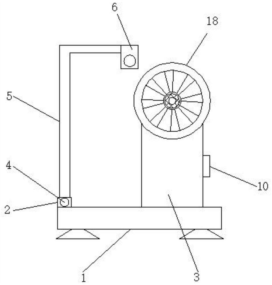
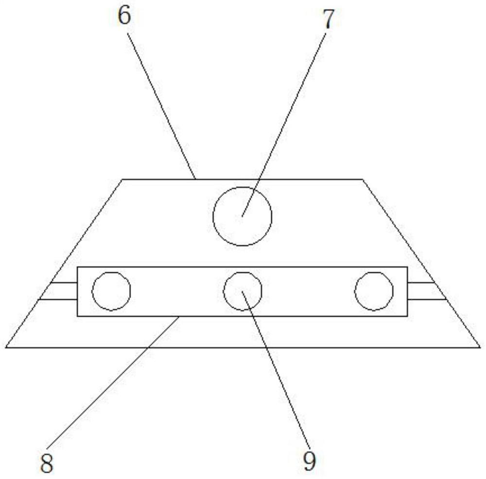
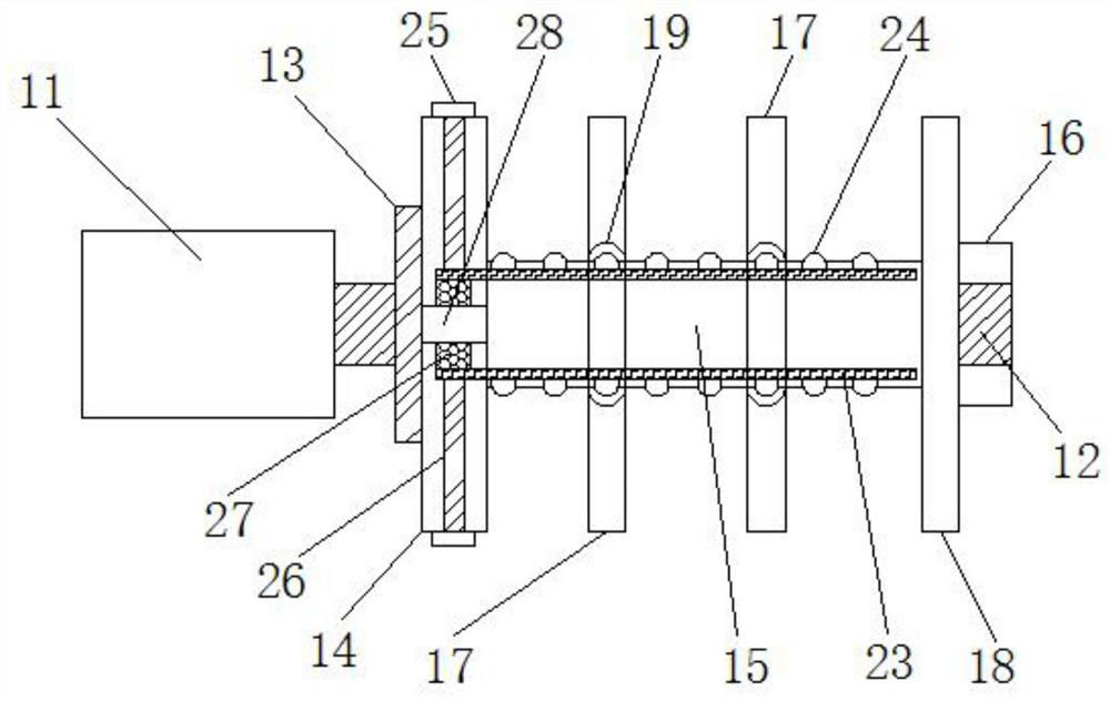
A textile equipment pay-off device with good shock-absorbing effect

A technology of textile equipment and shock absorption effect, which is applied in the field of pay-off device, which can solve the problems of large vibration amplitude, textile thread detached from the wire roller, and weaken the stability of the wire roller, so as to reduce the vibration amplitude, improve the shock absorption effect, and increase the use of range effect

Active Publication Date: 2020-11-24
嘉兴市康芙德纺织有限公司
View PDF11 Cites 0 Cited by
  • Summary
  • Abstract
  • Description
  • Claims
  • Application Information

AI Technical Summary

Problems solved by technology

[0002] At present, there are still some deficiencies in the existing textile equipment pay-off devices. For example, the existing textile equipment pay-off devices cannot limit the position of the textile thread during the transportation process, which may easily cause the textile thread to break away from the wire roller. phenomenon, and the vibration amplitude transmitted from the motor shaft to the wire roller during the use of the existing textile equipment pay-off device is relatively large, which weakens the stability of the wire roller during use, and easily causes the textile thread on the wire roller to be entangled. The shock absorption effect during the use of the wire roller is reduced. The use range of the existing textile equipment pay-off device is generally only a single pay-off, which reduces the flexibility of the pay-off device during use.

Method used


Image

  • A textile equipment pay-off device with good shock-absorbing effect
  • A textile equipment pay-off device with good shock-absorbing effect
  • A textile equipment pay-off device with good shock-absorbing effect

Examples


Embodiment Construction

[0024] The following will clearly and completely describe the technical solutions in the embodiments of the present invention with reference to the accompanying drawings in the embodiments of the present invention. Obviously, the described embodiments are only some of the embodiments of the present invention, not all of them.

[0025] In describing the present invention, it should be understood that the terms "upper", "lower", "front", "rear", "left", "right", "top", "bottom", "inner", " The orientation or positional relationship indicated by "outside", etc. is based on the orientation or positional relationship shown in the drawings, and is only for the convenience of describing the present invention and simplifying the description, rather than indicating or implying that the referred device or element must have a specific orientation, so as to Specific orientation configurations and operations, therefore, are not to be construed as limitations on the invention.

[0026] see ...


PUM


Abstract

The invention discloses a textile equipment thread unwinding device with a good damping effect. The device structurally comprises a base; the base is provided with a connecting plate and a driving box; a fixed shaft is arranged on the connecting plate; a support rod is arranged on the fixed shaft; a limiter is arranged at the right end of the support rod; a threaded hole, a thread penetrating shaft and thread holes are arranged on the limiter; the threaded hole is positioned in middle of the limiter; the thread penetrating shaft is fixedly connected to the middle lower side of the limiter; andthe thread holes are uniformly distributed in the outer surface of the thread penetrating shaft. The device effectively limits the stability of textile threads in the conveying process, prevents thetextile threads from being deviated from a thread roller, reduces the amplitude of vibration transferred to the thread roller from a motor rotating shaft, improves the use stability of the thread roller, prevents the winding phenomenon of the textile threads on the thread roller, and improves the damping effect in the use process of the thread roller and the flexibility in the use process of the thread unwinding device.

Description

technical field [0001] The invention relates to the technical field of pay-off devices, in particular to a pay-off device for textile equipment with good shock-absorbing effect. Background technique [0002] At present, there are still some deficiencies in the existing textile equipment pay-off devices. For example, the existing textile equipment pay-off devices cannot limit the position of the textile thread during the transportation process, which may easily cause the textile thread to break away from the wire roller. phenomenon, and the vibration amplitude transmitted from the motor shaft to the wire roller during the use of the existing textile equipment pay-off device is relatively large, which weakens the stability of the wire roller during use, and easily causes the textile thread on the wire roller to be entangled. The shock absorption effect during the use of the wire roller is reduced, and the range of use of the existing textile equipment pay-off device is general...

Claims


Application Information

Patent Timeline
Patent Type & Authority Patents(China)
IPC IPC(8): B65H49/30
CPCB65H49/30
Inventor 不公告发明人
Owner 嘉兴市康芙德纺织有限公司
Why Eureka
Try Eureka