Hemming clamp for luggage handle
A fixture and crimping technology, which is applied in the field of crimping fixtures for luggage handles, can solve problems such as low efficiency, low processing quality, and dimensional errors, and achieve the effects of ensuring product quality, improving work efficiency, and improving stability
- Summary
- Abstract
- Description
- Claims
- Application Information
AI Technical Summary
Problems solved by technology
Method used
Image
Examples
Embodiment 1
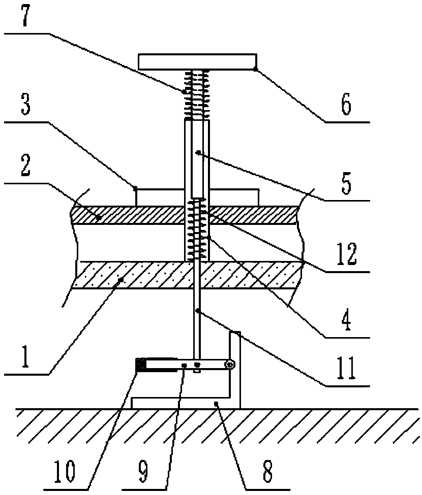
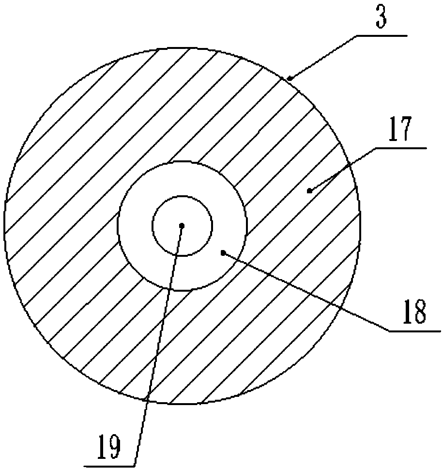
[0023] see Figure 1-3 , a crimping fixture for luggage handles, comprising a fixture body, the fixture body is arranged on a wire body 1, a transmission belt 2 is arranged above the wire body 1, and a groove 3 is arranged on the upper end surface of the transmission belt 2, so that The placement groove 3 and the transmission belt 2 are fixedly connected through the action of fixing screws, and the interior of the placement groove 3 is provided with a rubber pad 17, and the rubber pad 17 and the inner wall of the placement groove 3 are pasted by glue connection, the middle position of the placement groove 3 is provided with a handle limiting groove 18, and the inner side of the handle limiting groove 18 is provided with a pad 19, and between the pad 19 and the inner wall of the handle limiting groove 18 Paste and connect through the effect of glue, the clamp body is provided with a sleeve 4, the bottom of the sleeve 4 is arranged on the line body 1, and the sleeve 4 and the li...
Embodiment 2
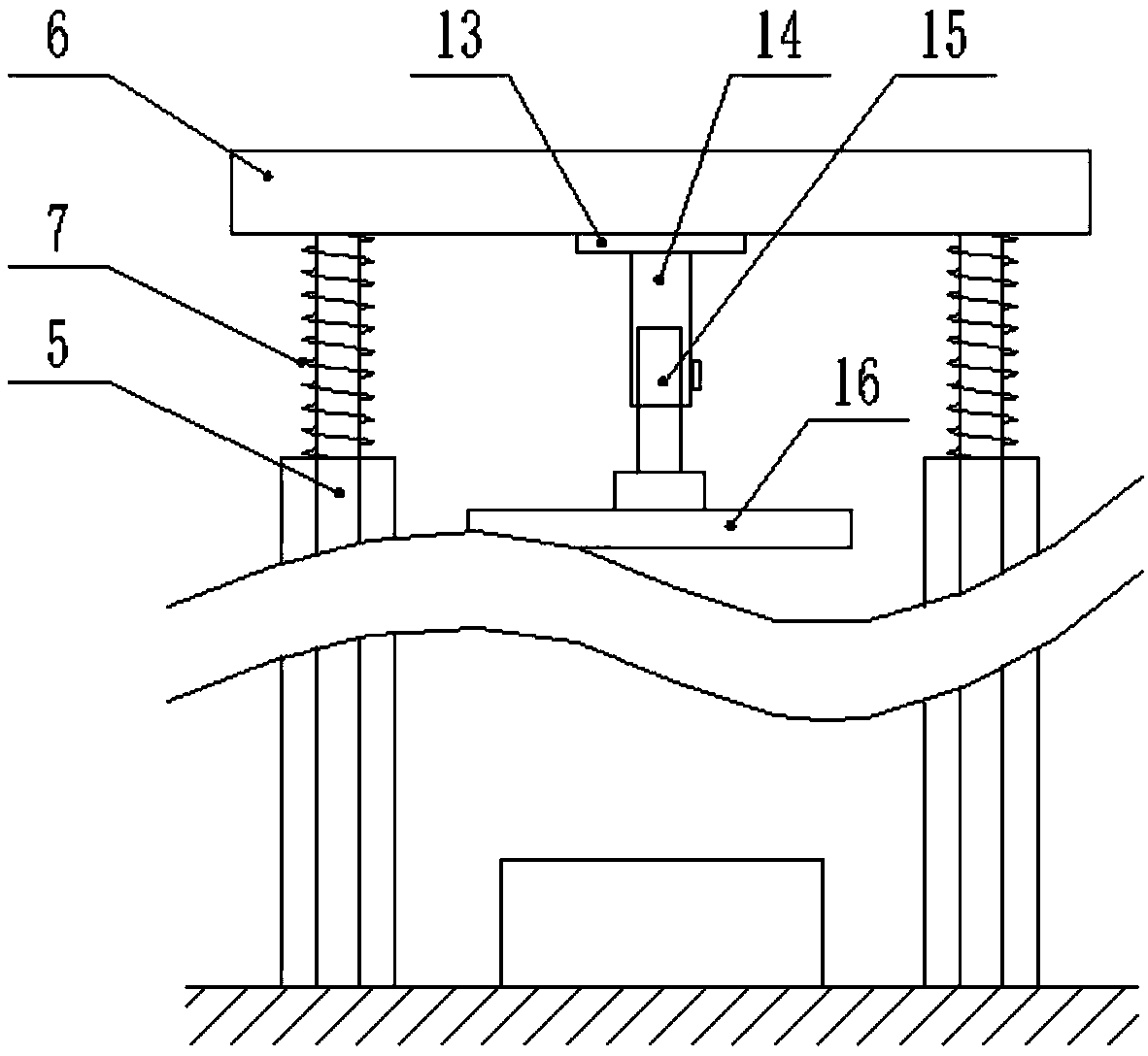
[0026] see Figure 1-2 and Figure 4, a crimping fixture for luggage handles, comprising a fixture body, the fixture body is arranged on a wire body 1, a transmission belt 2 is arranged above the wire body 1, and a groove 3 is arranged on the upper end surface of the transmission belt 2, so that The placement groove 3 and the transmission belt 2 are fixedly connected through the action of fixing screws, and the interior of the placement groove 3 is provided with a rubber pad 17, and the rubber pad 17 and the inner wall of the placement groove 3 are pasted by glue connection, the middle position of the placement groove 3 is provided with a handle limiting groove 18, and the inner side of the handle limiting groove 18 is provided with a pad 19, and between the pad 19 and the inner wall of the handle limiting groove 18 Paste and connect through the effect of glue, the clamp body is provided with a sleeve 4, the bottom of the sleeve 4 is arranged on the line body 1, and the sleev...
Embodiment 3
[0029] see Figure 1-2 and Figure 5 , a crimping fixture for luggage handles, comprising a fixture body, the fixture body is arranged on a wire body 1, a transmission belt 2 is arranged above the wire body 1, and a groove 3 is arranged on the upper end surface of the transmission belt 2, so that The placement groove 3 and the transmission belt 2 are fixedly connected through the action of fixing screws, and the interior of the placement groove 3 is provided with a rubber pad 17, and the rubber pad 17 and the inner wall of the placement groove 3 are pasted by glue connection, the middle position of the placement groove 3 is provided with a handle limiting groove 18, and the inner side of the handle limiting groove 18 is provided with a pad 19, and between the pad 19 and the inner wall of the handle limiting groove 18 Paste and connect through the effect of glue, the clamp body is provided with a sleeve 4, the bottom of the sleeve 4 is arranged on the line body 1, and the slee...
PUM
 Abstract
Description
Claims
Application Information
 - R&D
- Intellectual Property
- Life Sciences
- Materials
- Tech Scout
- Unparalleled Data Quality
- Higher Quality Content
- 60% Fewer Hallucinations
Browse by: Latest US Patents, China's latest patents, Technical Efficacy Thesaurus, Application Domain, Technology Topic, Popular Technical Reports.
© 2025 PatSnap. All rights reserved.Legal|Privacy policy|Modern Slavery Act Transparency Statement|Sitemap|About US| Contact US: help@patsnap.com


