
A v-cone flowmeter with bionic microstructure on the surface

A microstructure and flowmeter technology, which is applied to the volume/mass flow generated by mechanical effects, and the direction of fluid flow detection by measuring differential pressure. The effect of coefficient, energy saving and flow resistance reduction

Active Publication Date: 2020-04-21
潍坊亚峰化工仪表有限公司
View PDF14 Cites 0 Cited by
  • Summary
  • Abstract
  • Description
  • Claims
  • Application Information

AI Technical Summary

Problems solved by technology

It is worth noting that although the pressure loss of the V-cone flowmeter is much lower than that of the orifice flowmeter, compared with the Venturi flowmeter, it still has the defects of larger pressure loss and lower outflow coefficient, which restricts its further promotion. use

Method used


Image

  • A v-cone flowmeter with bionic microstructure on the surface
  • A v-cone flowmeter with bionic microstructure on the surface
  • A v-cone flowmeter with bionic microstructure on the surface

Examples


Embodiment approach 1

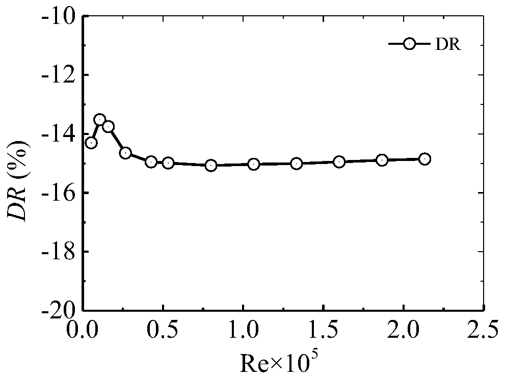
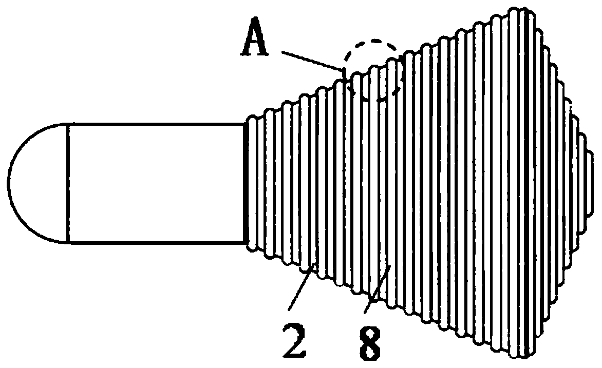
[0039] The rib microstructure is arranged on the surface of the V-shaped cone, and the schematic diagram is as follows image 3 shown. The ribs are arranged circumferentially along the surface of the cone, with a semicircular or arc-shaped cross section. The width of the ribs is W, the height is H, and the distance between adjacent ribs is L. The ratio of the width W of the rib cross-section to the height H, W:H=2:1~4:1, the distance L between adjacent ribs is, L=(0~2)W, preferably, when W:H=2: 1. When L=W, the V-cone flowmeter has the best drag reduction effect. Define the rent reduction rate DR as

[0040]

[0041] In the formula, Δω′ is the pressure loss after microstructures are arranged on the surface of the V-cone flowmeter cone, and Δω is the pressure loss without microstructures on the surface of the V-cone flowmeter cone.

[0042] When DR is a negative value, it indicates that the flow resistance of the V-cone flowmeter decreases, otherwise, the flow resistance ...

Embodiment approach 2

[0044] Groove microstructures are arranged on the surface of the V-shaped cone, and the schematic diagram is as follows Figure 5 and Figure 6 shown. The grooves are arranged circumferentially along the surface of the cone. The cross-sectional shape of the grooves is arc-shaped or semicircular. The ratio of the width W of the groove cross-section to the height H is W:H=2:1~4:1, adjacent The rib spacing L is, L=(0-2)W, preferably, when W:H=2:1, L=W, the V-cone flowmeter has the best drag reduction effect.

Embodiment approach 3

[0046] The convex hull microstructure is arranged on the surface of the V-shaped cone, and the schematic diagram is as follows Figure 7 and Figure 8 shown. The cross-sectional shape of the convex hull is arc-shaped or semicircular, and the ratio of the width W to the height H of the groove cross-section is W:H=2:1-4:1. The number of convex hulls is multiple, and they are aligned vertically and horizontally on the surface of the V-shaped cone, arranged in a criss-cross pattern on the surface of the V-shaped cone, or arranged irregularly on the surface of the V-shaped cone.


PUM


Abstract

The invention discloses a V-cone flowmeter with bionic microstructures on the surface. The flowmeter comprises a pipe, a V-shaped cone, a supporting rod and a low-pressure tapping pipe. The V-shaped cone is fixed to the interior of the pipe through the supporting rod, multiple microstructures are arranged on the surface of the V-shaped cone, and a high-pressure tapping pipe and a restoration pressure tapping pipe are further arranged on the pipe; the high-pressure tapping pipe is located on the upstream of the V-shaped cone, the restoration pressure tapping pipe is located on the downstream ofthe V-shaped cone, and the low-pressure tapping pipe is located between the high-pressure tapping pipe and the restoration pressure tapping pipe; the low-pressure tapping pipe penetrates through thesupporting rod and is communicated with the low-pressure tapping face of the top point of a rear cone body of the V-shaped cone in sequence. One or two or more kinds of bionic microstructures such asribs, grooves, bosses and pits are distributed on the surface of the V-shaped cone, parameters such as the ratio of width to height, spacing, number and distribution modes of the microstructures are reasonably set, optimal structure parameters of the microstructures on the surface are obtained, and finally the resistance reduction aim is achieved.

Description

technical field [0001] The invention belongs to the technical field of flow measurement, in particular to a V-cone flowmeter with a bionic microstructure on the surface. Background technique [0002] The V-cone flowmeter is a side-wall contraction-type throttling differential pressure flowmeter. Its V-shaped cone is installed in the measuring tube coaxially with the pipe. The fluid gradually throttles through the cone and shrinks to the vicinity of the inner wall of the pipe. A differential pressure is created across the cone. Among them, the high-pressure pressure inlet is located on the pipe wall before the fluid shrinks upstream of the V-cone, and the low-pressure pressure inlet is located at the central axis of the cone on the downstream end of the cone, passing through the cone, and leading out of the pipe through the support rod. The structural characteristics of the V-cone flowmeter make the fluid gradually shrink to the inner wall of the tube, so it has a series of ...

Claims


Application Information

Patent Timeline
Patent Type & Authority Patents(China)
IPC IPC(8): G01F1/34
CPCG01F1/34
Inventor 贺登辉许华丹黄寅峰张振铎张洁黄锐
Owner 潍坊亚峰化工仪表有限公司
Learn More