A hardware encoding and decoding method built in MCU for realizing industrial bus communication

An encoding and decoding method and industrial bus technology, applied in the field of fire protection, can solve problems such as delay encoding uncertainty, affecting decoding accuracy, increasing system power consumption, etc., to ensure stability and consistency, and meet timing requirements. The effect of enhancing the ability of anti-interference

Active Publication Date: 2020-03-24
SICHUAN SAIKE SECURITY TECH CO LTD +1
View PDF13 Cites 0 Cited by
  • Summary
  • Abstract
  • Description
  • Claims
  • Application Information

AI Technical Summary

Problems solved by technology

Due to the difference in performance between different MCUs, using the above method will lead to different delay times for entering interrupts. At this time, coupled with the generation of other external interrupts, it will eventually cause uncertain delays in interrupts, which in turn affects the decoding. precision
[0004] And because the fire bus is generally encoded by pulse width, the uncertain delay will also lead to uncertain problems in encoding
Since the fire bus communication has very high timing requirements, the use of pure software will cause strong interference to the entire fire protection system, seriously affecting the stability and consistency of the system
[0005] In addition, in the existing industrial bus encoding and decoding process, the pulse width value is stored in the form of an array by the MCU software, which requires the MCU to work continuously at high frequency. The power consumption of the system also affects the transmission distance of the signal, and in the development process, the software writing is more difficult and time-consuming

Method used


Image

  • A hardware encoding and decoding method built in MCU for realizing industrial bus communication
  • A hardware encoding and decoding method built in MCU for realizing industrial bus communication

Examples


Embodiment Construction

[0039] The present invention will be further described below with reference to the accompanying drawings and embodiments, and the mode of the present invention includes but not limited to the following embodiments.

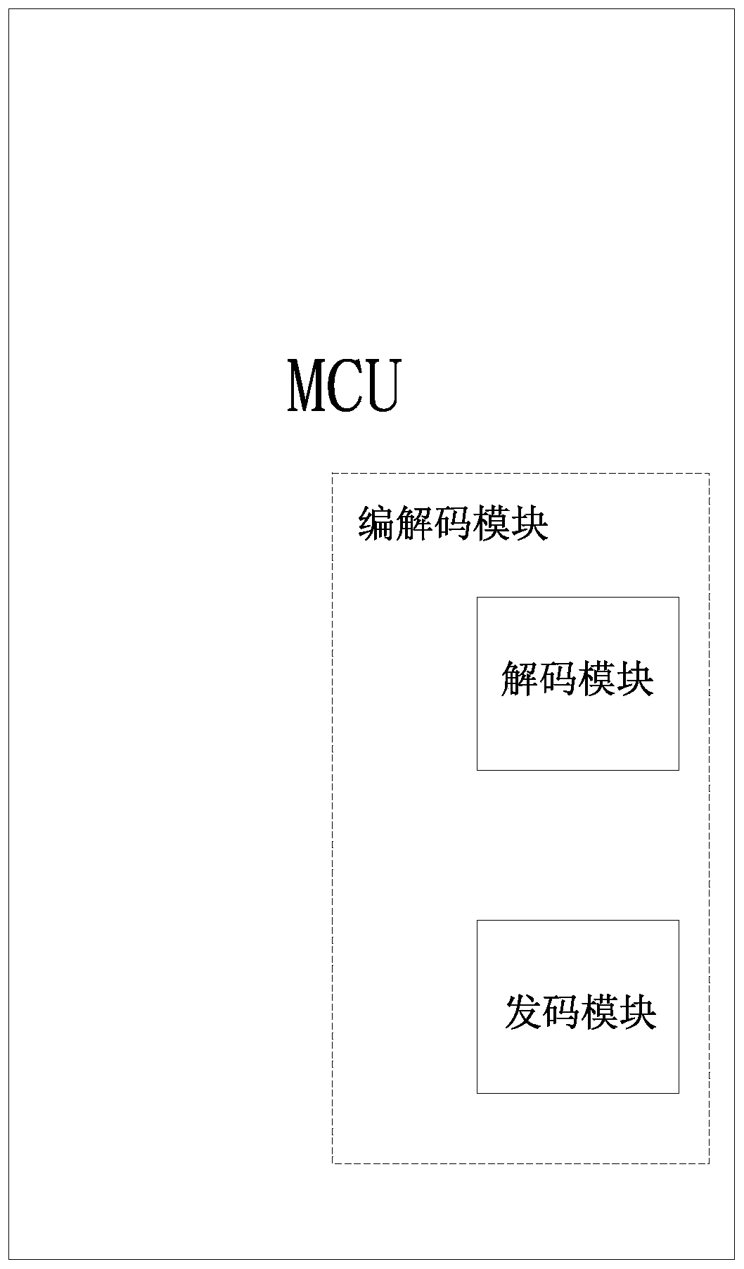
[0040] Such as figure 1 As shown, the present invention provides a codec module, which can be built into the MCU, and realizes the communication of the industrial bus by cooperating with the hardware of the MCU and combined with the design of the software flow. The encoding and decoding module of the present invention can automatically judge the width of the pulse signal when in use and analyze it into a digital signal and store it in the MCU, then modulate the fixed value of the pulse width corresponding to the data bit by bit when sending, and finally use the high and low sent in the form of level.

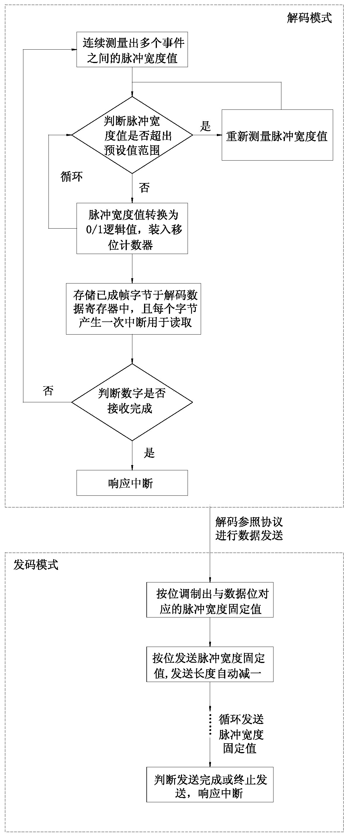
[0041] In order to realize the above-mentioned functions, the workflow of the present invention is divided into a decoding mode and a coding mode (such as figure...


PUM


Abstract

The invention discloses a hardware encoding and decoding method built in an MCU for realizing industrial bus communication. The method comprises an encoding and decoding module built in an MCU. The encoding and decoding module is composed of a decoding module and a code transmitting module, wherein the decoding module is used for measuring pulse widths among a plurality of events, analyzing the pulse widths into digital signals and storing the digital signals in a decoded data register of the MCU; the code transmitting module is used for modulating the digital signals into corresponding pulsewidth data, storing the pulse width data in the code transmitting data register of the MCU, and transmitting the pulse width data in the form of high-low level. A self-designed decoding mode and a self-designed code transmitting mode are adopted to realize encoding and decoding of industrial bus pulse signals. In this way, the method fundamentally solves the technical problems existing in conventional modes, can ensure the timing of bus communication, can reduce development difficulties and costs, is high in encoding and decoding accuracy, and ensures the stability, consistency and signal transmission distance of the system as a whole. Therefore, the method is suitable for popularization and application.

Description

technical field [0001] The invention relates to the technical field of fire protection, in particular to a hardware encoding and decoding method built in an MCU for realizing industrial bus communication. Background technique [0002] At present, most of the industrial buses use MBUS, CAN, RS485 and other buses for communication. Among these buses, only MBUS or other specific fire-fighting buses can realize power supply bus communication. [0003] Since there is no uniform standard, the performance of the fire bus in the fire protection industry is uneven, such as power supply performance or intelligence. Especially in order to realize the decoding on the industrial bus, it is all realized by pure software: for example, through the external interrupt + Timer of the MCU to cooperate with the generation of recording events. Due to the difference in performance between different MCUs, using the above method will lead to different delay times for entering interrupts. At this ti...

Claims


Application Information

Patent Timeline
Patent Type & Authority Patents(China)
IPC IPC(8): G05B19/042
CPCG05B19/0426G05B2219/23146
Inventor 不公告发明人
Owner SICHUAN SAIKE SECURITY TECH CO LTD
Why Eureka
Try Eureka