Mower

A lawnmower and casing technology, which is applied in the field of lawnmowers, can solve problems such as inability to meet the needs of convenient switching and locking of the handle, complicated handle structure, and inconvenient operation.

Pending Publication Date: 2018-12-11
ZHEJIANG YAT ELECTRICAL APPLIANCE CO LTD
View PDF12 Cites 0 Cited by
  • Summary
  • Abstract
  • Description
  • Claims
  • Application Information

AI Technical Summary

Problems solved by technology

However, the existing lawnmower handle has a complex structure and is inconvenient to operate, and cannot satisfy the fast and conveni

Method used


Image

  • Mower
  • Mower
  • Mower

Examples


Embodiment 1

[0032] see Figure 1-9 .

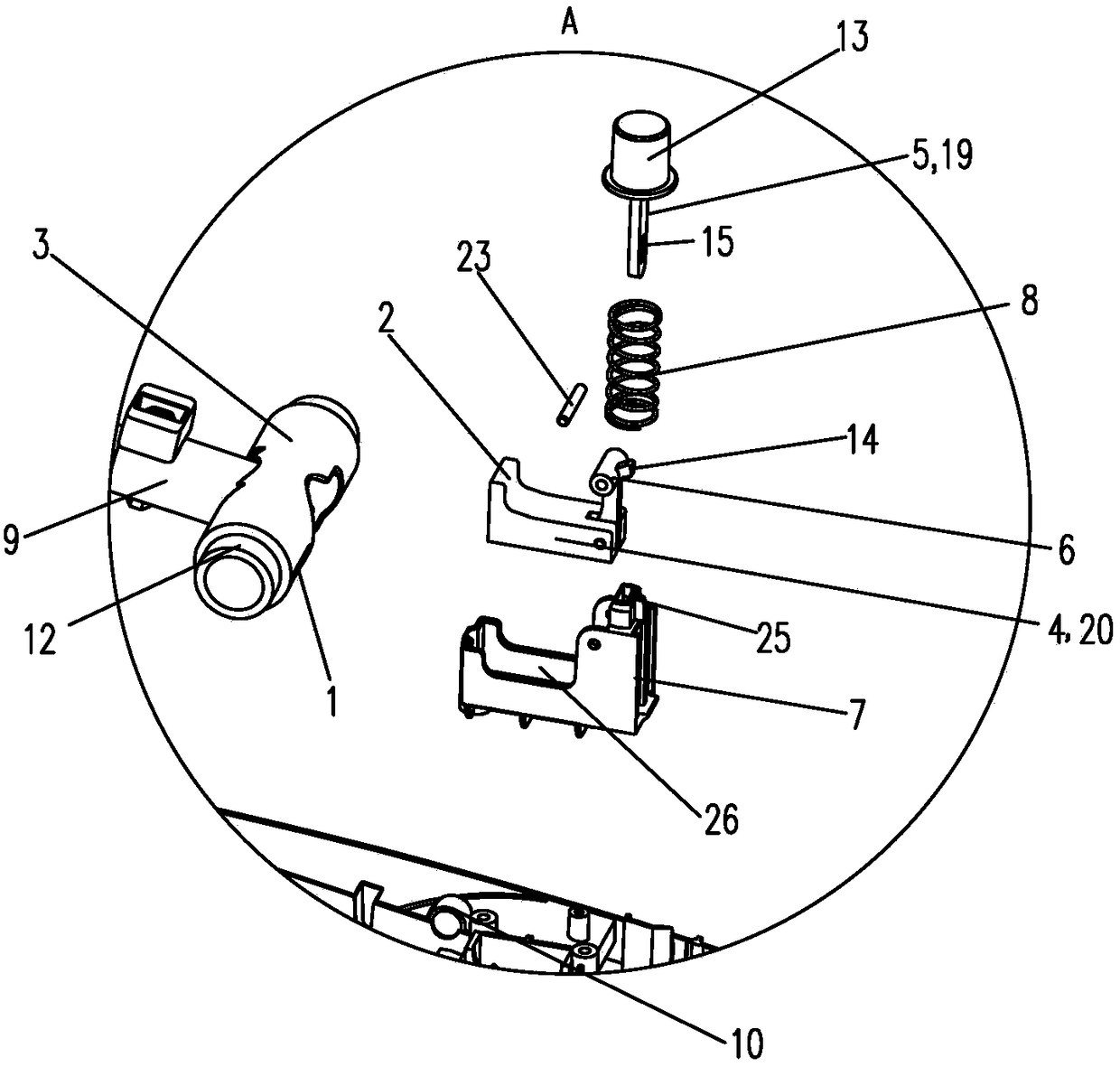
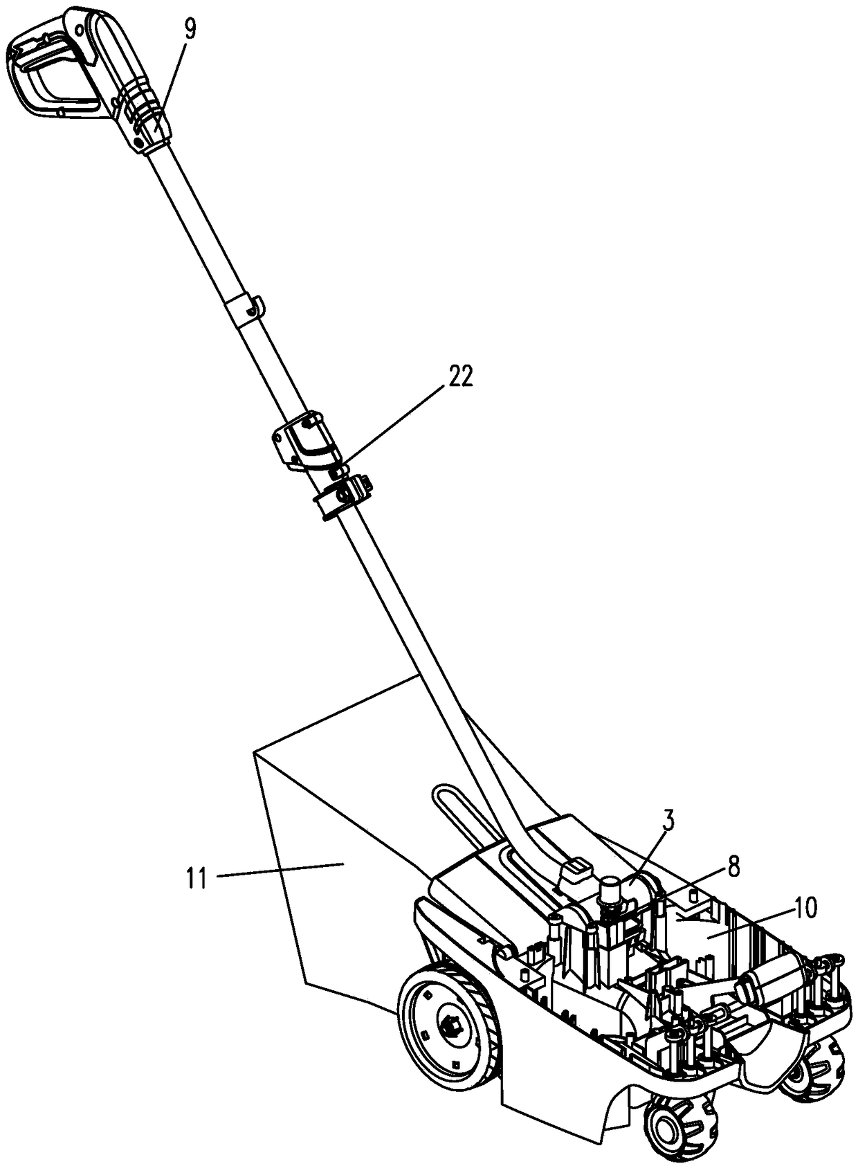
[0033] This embodiment provides a lawn mower, including a handle 9, a casing 10, a locking groove 1, a locking member 2 and a control part, the handle 9 is rotatably arranged on the casing 10, the locking groove 1 and the locking One of the parts 2 is arranged on the handle 9, and the other is arranged on the casing 10. The control part is used to control the translation of the locking part 2 in and out of the locking groove 1, and the locking groove 1 and the locking part 2 are used to limit the handle. 9 relative casing 10 rotates.

[0034] The main difference between the different operating states of the mower is the angle between the handle 9 and the casing 10 . When switching the running state of the lawn mower, the locking part 2 is first moved out of the locking groove 1 through the control part, and the handle 9 is unlocked. At this time, the handle 9 can be rotated relative to the casing 10, and then the handle 9 is turned to make the hand...

Embodiment 2

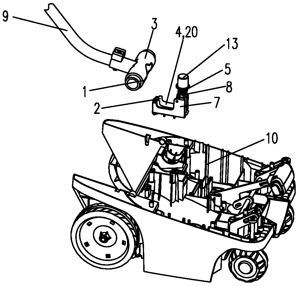
[0059] see Figure 10-11 , in this embodiment, the handle 9 drives the rotating seat 3 to rotate, the control member 5 is the first rack 16, the locking seat 4 is the second rack 17, the steering member 6 is a gear 18, and a second gear is inserted on the gear 18. No. rotating rod 24, No. two rotating rod 24 are fixed on the base 7, and gear 18 is installed on the base 7 around the second rotating rod 24 rotation. The base 7 is provided with the No. 2 vertical socket 27 along the vertical direction, and the first rack 16 is movably installed in the No. 2 vertical socket 27 along the vertical direction, and the base 7 is provided with the No. 2 horizontal socket 27 along the horizontal direction. The guide groove 28 and the second rack 17 are movably installed in the No. 2 horizontal guide groove 28 along the horizontal direction. The gear 18 includes a first gear 29 and a second gear 30 , the first rack 16 meshes with the first gear 29 , and the second gear 30 meshes with the...


PUM


Abstract

The invention discloses a mower, and belongs to the field of mowers. The mower comprises a handle, an enclosure, a locking groove, a locking member and a control unit, wherein the handle is rotatablyarranged on the enclosure, one of the locking groove and the locking member is arranged on the handle, the other is arranged on the enclosure, the control unit is used for controlling the locking member to parallelly move in and out of the locking groove, and the locking groove and the locking member limit the rotation of the handle relative to the enclosure when the locking member is located in the locking groove. When the locking member is located in the locking groove, the handle and the enclosure are mutually locked and cannot realize relative rotation, and when the locking member is located outside the locking groove, the handle and the enclosure are mutually unlocked and can realize relative rotation. Switching of the locking state and unlocking state between the locking member and the locking groove is realized by parallelly moving the locking member in and out of the locking groove.

Description

【Technical field】 [0001] The invention relates to a lawnmower and belongs to the field of lawnmowers. 【Background technique】 [0002] The single-handle lawn mower needs to change frequently between the mowing state, carrying state, storage state and grass picking frame state, so the handle needs to meet the needs of convenient adjustment and fixing. However, the existing lawn mower handle has a complex structure and is inconvenient to operate, and cannot satisfy the fast and convenient switching and locking of the handle between various working states, which brings a lot of inconvenience to the user during use. 【Content of invention】 [0003] The technical problem to be solved by the present invention is to overcome the deficiencies of the prior art and provide a lawnmower, which is used to adjust the handle to different positions, quickly and conveniently realize the locking and unlocking of the handle, and then quickly and conveniently change the operating state of the l...

Claims


Application Information

Patent Timeline
IPC IPC(8): A01D75/00
CPCA01D75/00
Inventor 李君涛张文兵孙博文
Owner ZHEJIANG YAT ELECTRICAL APPLIANCE CO LTD
Why Eureka
Try Eureka