[0022] The technical solutions in the embodiments of the present invention will be clearly and completely described below with reference to the accompanying drawings in the embodiments of the present invention. Obviously, the described embodiments are only a part of the embodiments of the present invention, but not all of the embodiments. Based on the embodiments of the present invention, all other embodiments obtained by those of ordinary skill in the art without creative efforts shall fall within the protection scope of the present invention.
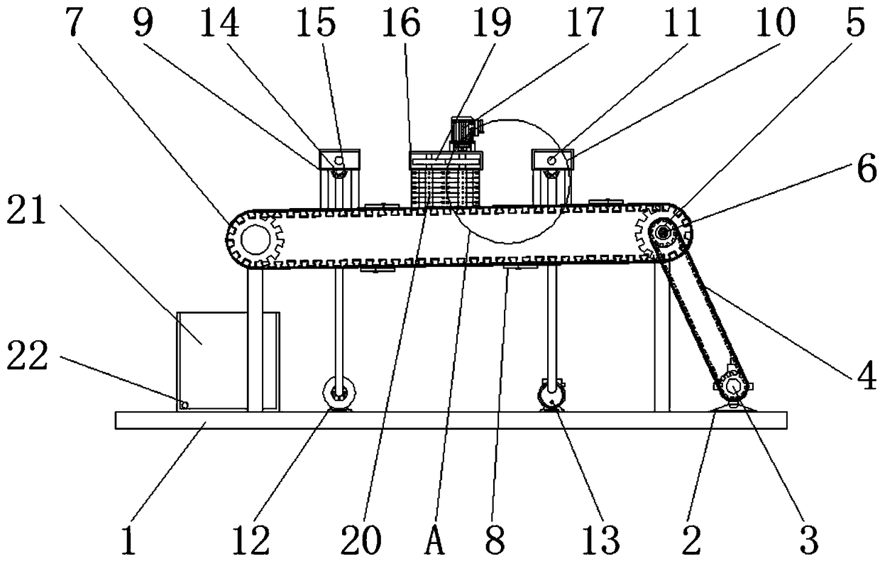
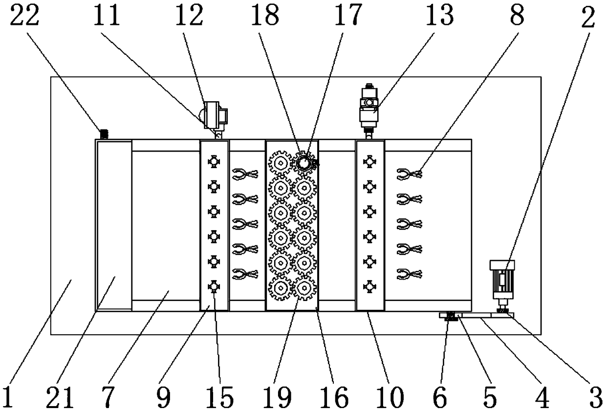
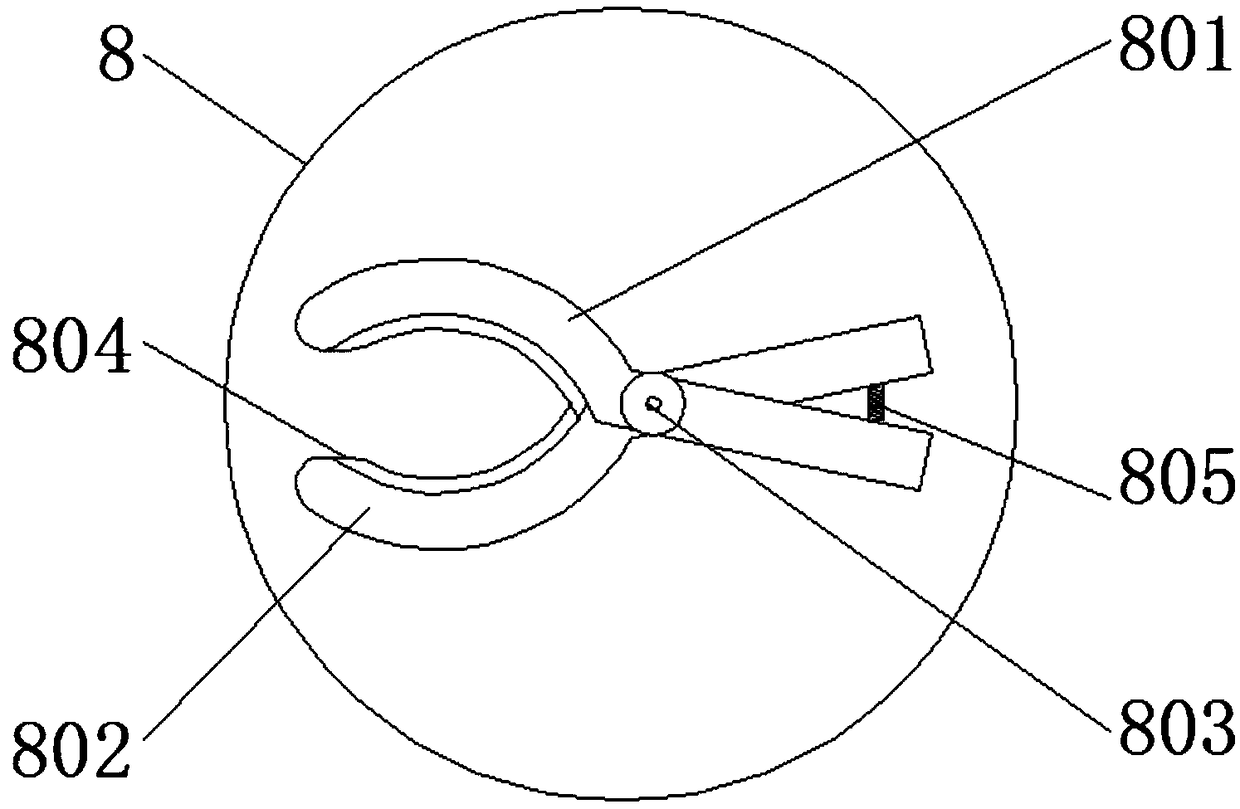
[0023] like Figure 1-4 As shown, the present invention provides a technical solution: a cleaning device for plastic products that is convenient for collecting waste liquid, comprising a base 1, a first motor 2, a first gear 3, a connecting belt 4, a second gear 5, and a first connecting rod 6. Conveyor belt 7, fixing clip 8, air storage block 9, water storage block 10, pipeline 11, fan 12, water pump 13, connecting block 14, spray head 15, brushing shell 16, second motor 17, third gear 18, first The four gears 19, the brush head 20, the waste liquid pool 21 and the connecting pipe 22, the first motor 2 is fixed at the lower left corner of the base 1, and the first gear 3 is connected in front of the first motor 2, and the first gear 3 passes through the connecting belt 4 is meshed with the second gear 5, and both the second gear 5 and the conveyor belt 7 are penetrated by the first connecting rod 6, and the conveyor belt 7 is located on the rear side of the second gear 5, and the outer side of the conveyor belt 7 is fixedly connected with a fixing clip 8, There are 4 sets of fixing clips 8 equidistantly arranged, and each set of fixing clips 8 is arranged equidistantly with 5 sets, so that the cleaning work of multiple plastic products can be completed at the same time, and the working efficiency of the device is increased. The fixing clips 8 include a first clip Block 801, second clamping block 802, second connecting rod 803, rubber block 804 and spring 805, the middle of the first clamping block 801 is hinged with the second clamping block 802 through the second connecting rod 803, and the right The side is connected with the second clamping block 802 through the spring 805, the left inner walls of the first clamping block 801 and the second clamping block 802 are attached with rubber blocks 804, and the upper left side of the conveyor belt 7 is provided with an air storage block 9, and The rear side of the air storage block 9 is connected to the fan 12 through a pipeline 11, a water storage block 10 is provided on the upper right side of the conveyor belt 7, and the rear side of the water storage block 10 is connected to the water pump 13 through a pipeline 11. The pipeline 11 and the storage A connecting block 14 is installed below the water block 10, and a nozzle 15 is welded on the outside of the connecting block 14. The shape of the connecting block 14 is hemispherical, and five nozzles 15 are uniformly welded under the connecting block 14, so that gas and water It can be sprayed around and below, which increases the range and time of cleaning and drying. A scrubbing shell 16 is provided between the air storage block 9 and the water storage block 10, and a second motor 17 is provided above the scrubbing shell 16, and A third gear 18 is connected below the second motor 17, the third gear 18 is meshed with the fourth gear 19, and both the fourth gear 19 and the third gear 18 are located inside the brushing housing 16, and the fourth gear 19 and the The brush heads 20 are connected below the three gears 18. The brush heads 20 respectively form a rotating structure through the third gear 18 and the fourth gear 19, and the fourth gear 19 and the third gear 18 are connected by meshing connection. The second motor 17 drives the third gear 18 to rotate, the brush head 20 is driven to rotate through the third gear 18 and the fourth gear 19, and the brush head 20 is used to brush plastic products, so that the cleaning is relatively clean. A waste liquid pool is installed on the lower left corner of the base 1 21, and a connecting pipe 22 is reserved on the rear side of the waste liquid pool 21.
[0024] like figure 1 The middle conveyor belt 7 , the second gear 5 and the first gear 3 constitute a linkage structure, and the conveyor belt 7 is arranged in an inclined manner, the conveyor belt 7 can be driven to rotate by the first motor 2 , and the second gear 5 and the first gear 3 A motor 2 is placed on the right side of the conveyor belt 7 to prevent the waste liquid on the conveyor belt 7 from accidentally falling on the first motor 2 and causing damage to the first motor 2, and the conveyor belt 7 is inclined so that the waste liquid flows along the conveyor belt 7 to the waste liquid In the tank 21, it is convenient to collect and process the waste liquid.
[0025] like image 3 In the middle, the first clamping block 801 and the second clamping block 802 both form a rotating structure on the second connecting rod 803, and the first clamping block 801 and the second clamping block 802 are distributed in a cross manner, and the first clamping block 801 and the second clamping block 801 and the second clamping block The shape of the left side of the block 802 is an arc line. By pressing the right side of the first clamping block 801 and the second clamping block 802, the left opening of the first clamping block 801 and the second clamping block 802 can be opened, and the plastic products can be opened. The house is on the left side of the first clamping block 801 and the second clamping block 802, and the plastic products can be fixed by the elastic action of the spring 805, so that the position of the plastic products can be prevented from changing during the cleaning process, and the cleaning effect is ensured.
[0026] When using, first open the first motor 2, the first motor 2 drives the connecting belt 4 to rotate through the first gear 3, the connecting belt 4 drives the second gear 5 to rotate, and the second gear 5 is connected to the conveyor belt 7 through the first connecting rod 6. Connect, then drive the conveyor belt 7 to rotate, then connect the water pump 13 with the water inlet pipe, and connect the connecting pipe 22 with the sewage pipe, and then turn on the water pump 13, the fan 12 and the second motor 17;
[0027] Then press the right side of the first clamp block 801 and the second clamp block 802, the first clamp block 801 and the second clamp block 802 will rotate along the second connecting rod 803, and open the first clamp block 801 and the second clamp block 802 The left opening, and then place the plastic products to be cleaned at the left opening of the first clamping block 801 and the second clamping block 802, and then release the first clamping block 801 and the second clamping block 802. The second clamping block 802 will press the left side of the first clamping block 801 and the second clamping block 802 inwards due to the elastic action of the spring 805, thereby fixing the plastic product on the fixing clamp 8, and the first clamping block 801 and the second clamping block 801 A rubber block 804 is provided on the left inner wall of the block 802, and the rubber block 804 functions as a plastic product;
[0028] Then, due to the rotation of the conveyor belt 7, the plastic products are conveyed to the right, the water pump 13 pressurizes the water and transmits it to the water storage block 10 through the pipeline 11, and then transmits it to the nozzle 15 through the connecting block 14. The lower part is directed to the plastic products to ensure that all surfaces of the plastic products can be washed. After the second motor 17 is turned on, the second motor 17 drives the third gear 18 to rotate, and the third gear 18 drives the fourth gear 19 to rotate. 19 are arranged at equal intervals in the brushing shell 16, and the fourth gear 19 is arranged in two rows. The brush head 20 is driven to rotate by the fourth gear 19 and the third gear 18. The pressure is transmitted to the air storage block 9 through the pipeline 11, and then transmitted to the nozzle 15 through the connecting block 14, and the air is injected into the plastic product from the surrounding and below through the nozzle 15 to dry the plastic product. That is, the first clamping block 801 and the second clamping block 802 can be removed by pressing, and the cleaning process of the plastic product is completed;
[0029] Since the conveyor belt 7 is inclined, the brushed liquid will flow to the left side of the conveyor belt 7 by the action of gravity, and finally fall into the waste liquid pool 21, and then be discharged into the sewage pipe through the connecting pipe 22 to complete the waste liquid collection of the device.
[0030] To sum up, 1. The plastic product cleaning device that is convenient for collecting waste liquid is provided with a water storage block 10, a brush head 20 and an air storage block 9, the connecting block 14 is hemispherical, and the connecting block 14 is evenly distributed with spray heads 15 , the spray head 15 sprays water and air around and below the connection block 14, and the brush heads 20 are arranged at equal distances, and the brush heads 20 are provided with 2 rows, and the brush heads 20 are driven to rotate by the action of the second motor 17, then the plastic The rinsing, brushing and drying of the product make the cleaning more sufficient, and it does not need to be dried, which saves time.
[0031] 2. The cleaning device for plastic products that is convenient for collecting waste liquid is provided with fixing clips 8. There are 4 sets of fixing clips 8, and each set of fixing clips 8 is provided with 5 pieces. Through the first clamping block 801 and the second clamping block 802 The plastic products can be fixed on the fixed clip 8, and the rotation of the conveyor belt 7 drives the plastic products on the fixed clip 8 to rotate, so that the cleaning of multiple plastic products can be completed at the same time, and the work efficiency is increased.
[0032] 3. The plastic product cleaning device for collecting waste liquid is provided with a conveyor belt 7, a waste liquid pool 21 and a connecting pipe 22, and the conveyor belt 7 is inclined so that the cleaned waste liquid can flow along the conveyor belt 7 to the left side of the conveyor belt 7, A waste liquid pool 21 is provided under the left side of the conveyor belt 7, and the waste liquid can be collected in the waste liquid pool 21. After the connecting pipe 22 is threadedly connected with the water outlet pipe, the waste liquid can be easily discharged. The first motor 2 is provided with There is the lower right side of the conveyor belt 7, and the water pump 13 and the fan 12 are arranged at the rear and bottom of the conveyor belt 7, so that water can be prevented from entering the first motor 2, the water pump 13 and the fan 12, and the durability of the device is increased.
[0033] Although embodiments of the present invention have been shown and described, it will be understood by those skilled in the art that various changes, modifications, and substitutions can be made in these embodiments without departing from the principle and spirit of the invention and modifications, the scope of the present invention is defined by the appended claims and their equivalents.