Steel truss welding methods for various angles

A welding method and steel truss technology, applied in the field of steel truss welding, can solve problems such as poor welding angle, low efficiency, and affecting quality of use, and achieve the effects of easy operation, good quality, and improved welding efficiency and quality

Active Publication Date: 2019-12-24
河北圣雄管件有限公司
View PDF4 Cites 0 Cited by
  • Summary
  • Abstract
  • Description
  • Claims
  • Application Information

AI Technical Summary

Problems solved by technology

[0004] The technical problem to be solved by the present invention is that the existing truss needs to be welded with multiple steel frames with different angles, and many people are needed to support the welding, and the welding angle is poor, so it is not only inefficient, but also affects the quality of later use , the purpose is to provide a steel truss welding method suitable for various angles, and solve the problem of welding steel pipes for trusses

Method used


Image

  • Steel truss welding methods for various angles
  • Steel truss welding methods for various angles

Examples


Embodiment 1

[0038] like figure 1 and figure 2 Shown, the present invention comprises the following steps:

[0039] (1) The steel pipe to be welded is fixedly placed on the second fixed plate 2;

[0040] (2) The first fixed plate 1 is located directly above the second fixed plate 2, and the first fixed plate 1 is provided with a first fixed plate 1 with one end passing through the side of the first fixed plate 1 and the other end inside the first fixed plate 1, on the horizontal plane. A groove 3, the side of the first groove 3 on the first fixed plate 1 is provided with a first telescopic rod 7 that can expand and contract in the vertical direction, and the upper end of the first telescopic rod 7 is connected with the first telescopic rod that can expand and contract in the horizontal direction. One end of the two telescopic rods 8 is connected, and the other end of the second telescopic rod 8 is vertically connected with the first support rod 9, and the first support rod 9 is connecte...

Embodiment 2

[0045] The steel truss welding method is suitable for various angles. The new welding device for welding steel trusses of the present invention includes steel pipes for welding trusses and a fixing device for fixing steel pipes. The fixing device includes a first fixing plate 1 and a second fixing plate. Two fixed plates 2, the first fixed plate 1 is located directly above the second fixed plate 2, and the first fixed plate 1 is provided with one end that runs through the side of the first fixed plate 1 and the other end is inside the first fixed plate 1, on a horizontal plane The first groove 3 on the top, the second fixed plate 2 is provided with a second groove 4 on the horizontal plane with two ends penetrating through the opposite two sides of the second fixed plate 2, and the inner bottom surface of the second groove 4 The spring plate 5 that can expand and contract along the width direction of the second groove 4 is set, and the two ends of the telescopic end of the spri...

Embodiment 3

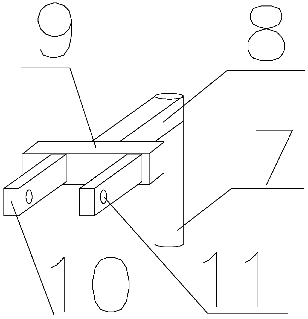
[0047] It is applicable to steel truss welding methods at various angles. On the basis of Embodiment 2, the clamping device includes two connecting plates 10 vertically arranged on the first support rod 9 at one end. The connecting plates 10 are located on the horizontal plane and located on the second Above a groove 3, a chute on the horizontal plane is provided on the surface connecting the first support rod 9 and the connecting plate 10, one end of the connecting plate 10 slides along the direction where the chute is located, and the other end of the connecting plate 10 is provided through There is a fixing groove 11, which is fixedly connected through bolts, and the steel pipe is fixed between two connecting plates 10, and the connecting plate 10 slides along the chute, and is fixedly connected to the steel pipe in between through the fixing groove 11 through the bolts. Several convex lines are arranged on two opposite surfaces of the connecting plate 10, and the convex lin...


PUM


Abstract

The invention discloses a welding method suitable for a steel truss of any angle. The welding method comprises the steps of fixedly placing one steel pipe to be welded onto a second fixed plate; fixing the other steel pipe to be welded to a clamping device; adjusting the length of a first telescopic rod and the length of a second telescopic rod to adjust the steel pipe to the required angle and enable the other steel pipe to make contact with the welding point of the steel pipe on the second fixed plate; arranging a welding device between a first fixed plate and the second fixed plate to conduct welding on the contact point of the two steel pipes; and rotating the first fixed plate and the second fixed plate to conduct welding on the other surface after completion of welding on the weldingpoint on one surface. The welding method has the advantages that the structure is simple, and operation and use are convenient.

Description

technical field [0001] The invention relates to the construction field, in particular to a steel truss welding method applicable to various angles. Background technique [0002] Steel trusses refer to trusses made of steel, roof structures such as crane girders, bridges, and hydraulic gates for industrial and civil buildings. Steel trusses are commonly used as the main load-bearing components. Various towers, such as mast towers, TV towers and transmission line towers, are commonly used as space steel trusses composed of three-sided, four-sided or multi-sided planar trusses. The most commonly used is the plane truss, and its stress is essentially a lattice beam under the action of lateral load. Compared with the steel beam of the solid web type, the steel truss is characterized by replacing the flange with the chord and the web with the web, and connecting the web at each node through the gusset plate (or other parts) with welds or other connections. The rods and chords ar...

Claims


Application Information

Patent Timeline
Patent Type & Authority Patents(China)
IPC IPC(8): B23K37/04B23K37/053
CPCB23K37/0443B23K37/0533
Inventor 黄欢
Owner 河北圣雄管件有限公司
Why Eureka
Try Eureka