Eureka AIR delivers breakthrough ideas for toughest innovation challenges, trusted by R&D personnel around the world.

Emergency Bridge Frame in Construction

A kind of technology in construction and bridge, applied in the direction of bridges, pedestrian bridges, bridge forms, etc., can solve problems such as vehicles cannot pass, and achieve the effect of convenient transportation

Inactive Publication Date: 2018-12-11
SUINING CHANGFENG MECHANICAL TECH
View PDF0 Cites 0 Cited by
  • Summary
  • Abstract
  • Description
  • Claims
  • Application Information

AI Technical Summary

Problems solved by technology

[0003] The purpose of the present invention is to overcome the shortcomings that vehicles cannot pass in the existing road construction, and provide a new type of bridge equipment, especially the emergency bridge during construction, hereinafter referred to as the bridge

Method used


Image

  • Emergency Bridge Frame in Construction
  • Emergency Bridge Frame in Construction
  • Emergency Bridge Frame in Construction

Examples


Embodiment Construction

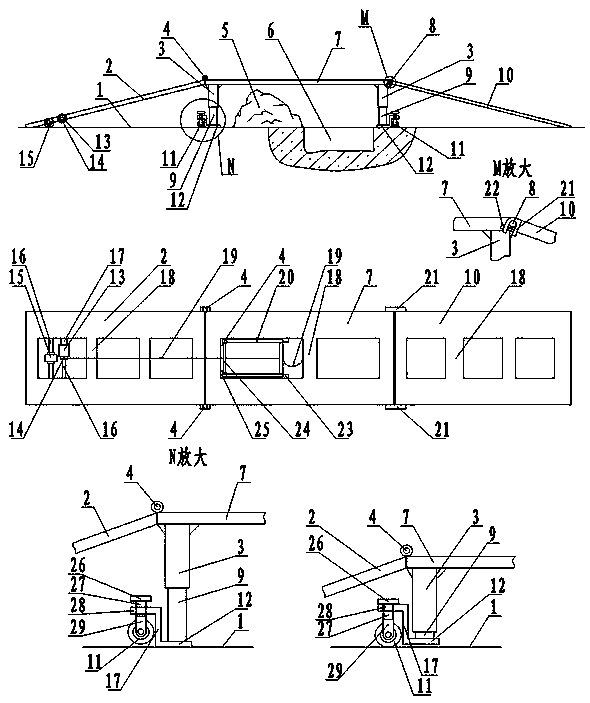
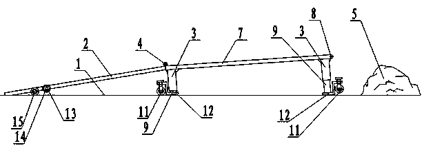
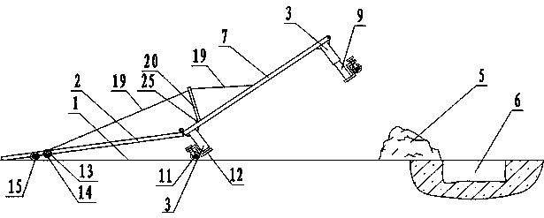
[0014] figure 1 In, is the bridge structure diagram. The picture above is the front view, and the third row is the top view. A transverse ditch6 was dug in the ground for construction. Concrete and earth crushed by impact are piled up into a slag ridge 5 on one side of the ditch 6 . Respectively connect a foot post cover 3 on four corners of main bridge frame 7 bottoms, the foot post cover 3 is a hollow square pipe. There are reinforcing ribs at both ends of the upper end of the foot column cover to connect with the main bridge frame. Foot column 9 is cuboid, and section is square. The foot column 9 is installed in the foot column cover 3 . The main bridge frame 7 front ends are connected and fixed with hanger pins 8 on the right side in the figure. As in the enlarged view of M, a hanging card 21 is installed on the upper end of the front auxiliary bridge frame 10, and the hanging card 21 is a fork shape. Hanging card 21 just forks on hanging card pin 8. A through hole...


PUM


Abstract

The invention relates to an emergency bridge under construction.The emergency bridge under construction includes a foot column sleeve,a foot column, a wheel lifting mechanism, a hydraulic cylinder, amain bridge frame, a front auxiliary bridge frame, a rear auxiliary bridge frame and ra etracting mechanism. At that low side of the four corners of the main bridge frame, foot post sleeve are installed. The foot post and the hydraulic cylinder are installed in the foot post sleeve. The foot board under the foot post is connected with the wheel lifting mechanism, so that the foot post touches theground when the bridge is open to traffic; When the bridge is moved, the wheels land and the legs are raised. The rear auxiliary bridge frame is hinged at the rear end of the main bridge frame, and the front auxiliary bridge frame is hung at the front end of the main bridge frame. Remove the front auxiliary bridge frame, pull up the front of the main bridge frame with the motor of the retracting and releasing mechanism, twisting wheels and pulling ropes, push the rear foot pillar of the main bridge frame to the side of the obstacle, and the front foot pillar crosses the obstacle and falls. Hang on to the front sub-axle frame and you can open to traffic. When folding, turn the rear auxiliary bridge frame onto the main bridge frame and put the front auxiliary bridge frame on the top of the main bridge frame so that the frame can be pulled away by trailer.

Description

technical field [0001] The invention belongs to the field of construction equipment, in particular to an emergency bridge during construction. Background technique [0002] In the present road installation pipeline construction, a ditch is often dug horizontally on streets and highways, and concrete and earth slag blocks are piled up into a slag ridge on the side of the ditch, making it impossible for vehicles to pass through. A large number of vehicles had to go around. Bring a lot of inconvenience to passing vehicle. Although some construction sites temporarily put a bridge frame on the ditch, there is difficulty in crossing obstacles above the ground, and it is inconvenient to retract and move the bridge frame. Contents of the invention [0003] The purpose of the present invention is to overcome the shortcomings of vehicles being impassable during existing road construction, and provide a new type of bridge equipment, especially an emergency bridge during constructio...

Claims


Application Information

Patent Timeline
Patent Type & Authority Applications(China)
IPC IPC(8): E01D15/10
CPCE01D15/10
Inventor 邹家福邹永平胡冬梅
Owner SUINING CHANGFENG MECHANICAL TECH
Why Eureka
Eureka Blog
Learn More