
Holders, gearboxes, clutches, brakes and vehicles

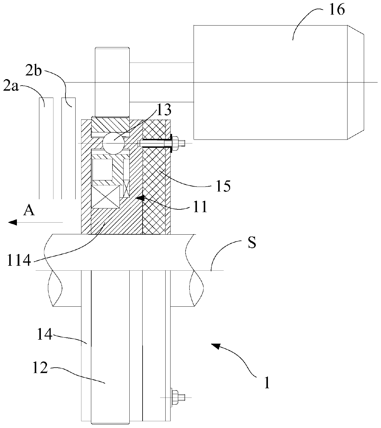
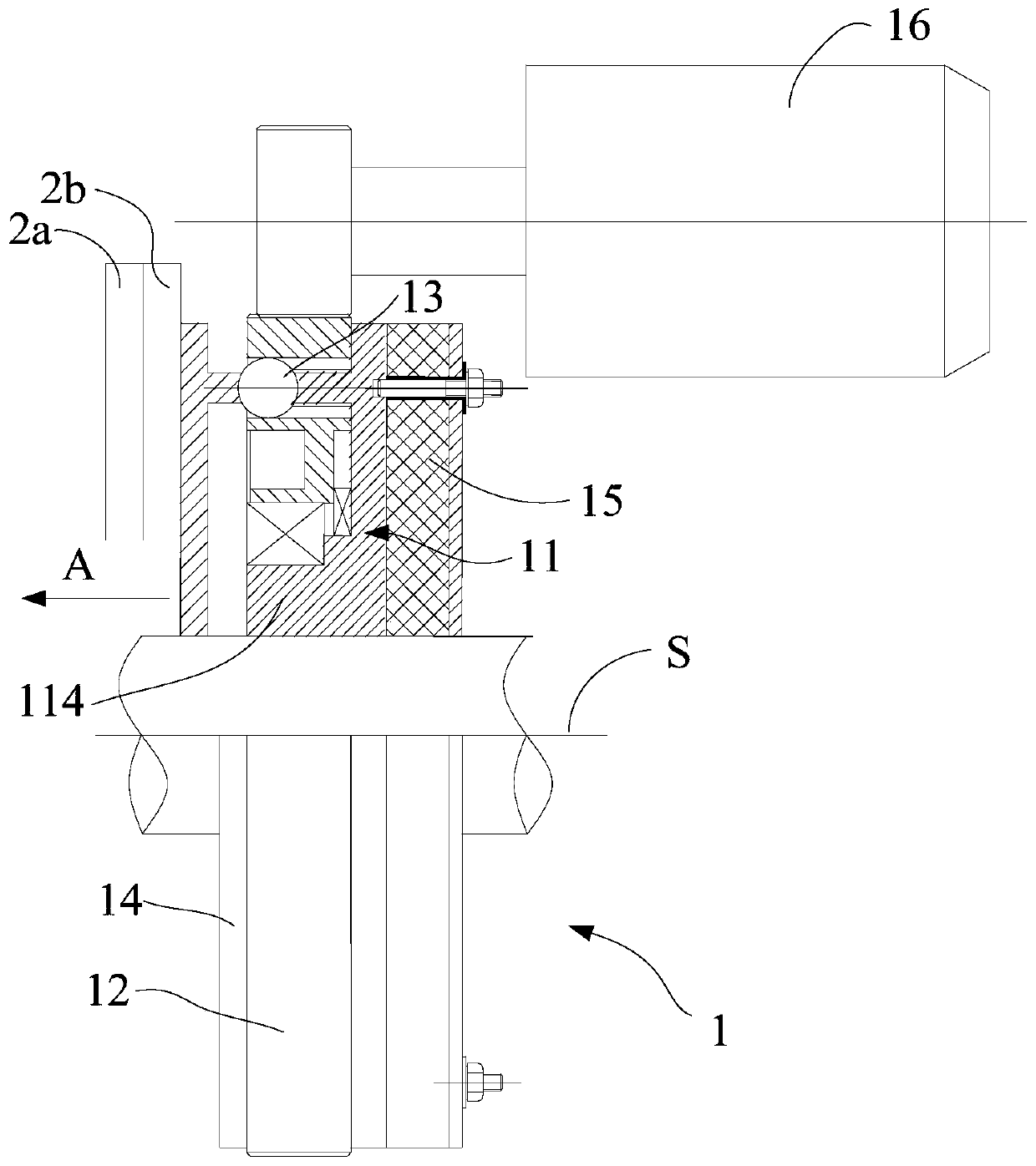
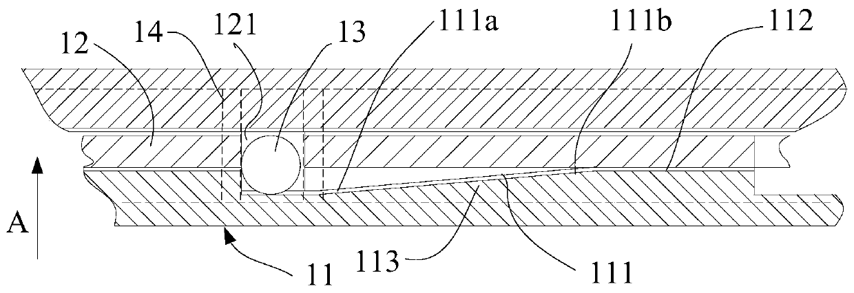
A technology of a pressing device and a pressing member, which is applied in the fields of gearboxes, clutches, brakes and vehicles and pressing devices, can solve the problems of difficulty in ensuring pressing force, slow response, and long operating time of the pressing device, and achieves Avoid insufficient pressing force and avoid self-locking effect

Active Publication Date: 2020-02-07
上海建麟汽车科技有限公司
View PDF6 Cites 0 Cited by
  • Summary
  • Abstract
  • Description
  • Claims
  • Application Information

AI Technical Summary

Problems solved by technology

In the case of limited space, the pressing device cannot be installed with a sufficiently large driving component, so it is difficult to ensure that the output of sufficient pressing force
In addition, in some cases, in order to achieve the required pressing force, a reduction mechanism with a large reduction ratio will be installed between the driving part and the piston, which will cause the pressing device to operate for a long time and react slowly.

Method used


Image

  • Holders, gearboxes, clutches, brakes and vehicles
  • Holders, gearboxes, clutches, brakes and vehicles
  • Holders, gearboxes, clutches, brakes and vehicles

Examples


Embodiment Construction

[0059] The implementation of the present invention will be illustrated by specific specific examples below, and those skilled in the art can easily understand other advantages and effects of the present invention from the content disclosed in this specification. Although the description of the present invention will be presented in conjunction with a preferred embodiment, it does not mean that the features of the invention are limited to this embodiment. On the contrary, the purpose of introducing the invention in conjunction with the embodiments is to cover other options or modifications that may be extended based on the claims of the present invention. The following description contains numerous specific details in order to provide a thorough understanding of the present invention. The invention may also be practiced without these details. Also, some specific details will be omitted from the description in order to avoid obscuring or obscuring the gist of the present invent...


PUM


Abstract

The invention provides a tight pressing device. The tight pressing device comprises a base, a roller retaining frame and a piston, wherein the base is provided with a roller way, the height of the roller way is increased from one end to the other end; the roller retaining frame is used for driving a roller body inside the roller retaining frame to roll along the roller way; the piston can be pushed to a pressing and fitting position from a reset position by the roller body; in a pressing and fitting stage, under the driving of a pressed part, the pressing force output by the tight pressing device can be automatically increased, so that the problem of insufficient pressing force possibly occurring in the prior art can be effectively avoided; in addition, the pressing force output by the tight pressing device is transmitted to the base through the roller body, and the pressing force is borne by the base; and an elastic assembly is installed on the base and is used for limiting the maximum pressing force output by the tight pressing device, and the problem that a self-locking problem easily occurs in the prior art is avoided; and the invention further provides a gearbox, a clutch, a brake and a vehicle which comprise the tight pressing device.

Description

technical field [0001] The invention relates to the field of mechanical transmission, in particular to a pressing device, a gearbox, a clutch, a brake and a vehicle including the pressing device. Background technique [0002] As the core components of the transmission, clutch and brake, the pressing device is responsible for the combination and separation of power. The driving parts of the pressing device mainly include: hydraulic drive, electric drive and cylinder drive. According to the different driving parts, the pressing device is also called hydraulic cylinder, electric cylinder and air cylinder. The driving part drives the piston to press or break away from the pressed part (such as the driven disc of the transmission, clutch or brake) to realize the combination or separation of power. [0003] In the existing pressing device, the pressing force is provided by the driving part (drive source) of the pressing device. In order to provide sufficient pressing force, the ...

Claims


Application Information

Patent Timeline
Patent Type & Authority Patents(China)
IPC IPC(8): F16D13/70F16D13/75
CPCF16D13/70F16D13/755
Inventor 蔡有建
Owner 上海建麟汽车科技有限公司
Learn More