A pressure-assisted precision machining method for thin-walled blanks
A technology of precision machining and blanks, applied in the field of precision machining of thin-walled blanks, it can solve the problems of inability to guarantee the shape and dimensional accuracy of the final parts, and achieve the effects of low cost, good versatility and reasonable design
- Summary
- Abstract
- Description
- Claims
- Application Information
AI Technical Summary
Problems solved by technology
Method used
Image
Examples
specific Embodiment approach 1
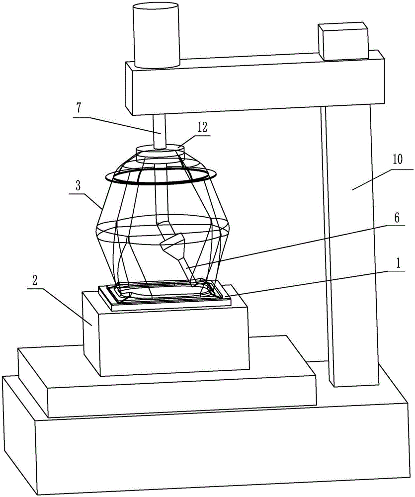
[0020] Specific implementation mode one: combine Figure 1-6 To illustrate, a pressure-assisted precision machining method for thin-walled blanks in this embodiment is implemented in accordance with the following steps:
[0021] Step 1, placing the blank 1 to be processed on the support tire mold 2;
[0022] Step 2, placing the pressure medium chamber 3 on the blank 1 to be processed, so that the lower end of the pressure medium chamber 3 is in close contact with the peripheral area of the blank 1 to be cut to realize sealing;
[0023] Step 3: Fill medium 5 into the pressure medium cavity 3, the pressure of the medium is 0.2-10MPa, and use the medium 5 to press the blank 1 to be cut tightly against the support tire mold 2;
[0024] Step 4, using the cutting tool 6 placed inside the pressure medium cavity 3 to cut the blank 1 to be cut to obtain the final required parts;
[0025] Step 5, remove the pressure in the pressure medium chamber 3, remove the cutting tool 6 and the...
specific Embodiment approach 2
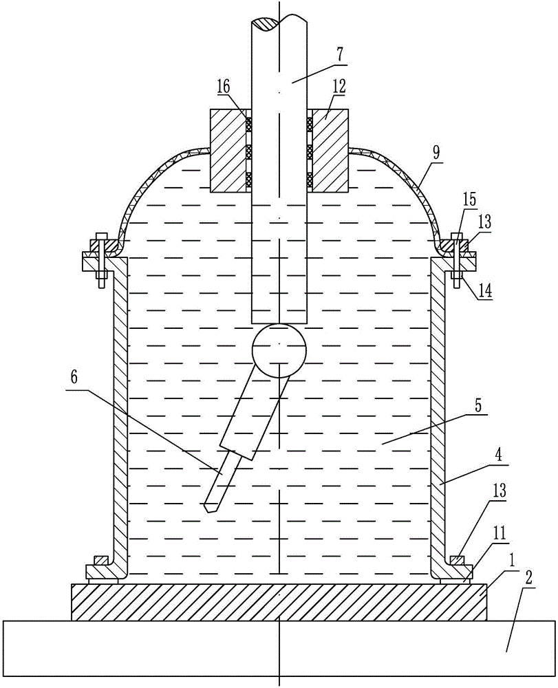
[0028] Specific implementation mode two: combination figure 1 , figure 2 , Figure 5 and Figure 7 Note that the pressure medium cavity 3 used in step 2 of this embodiment is a composite structure of a rigid pressure medium cylinder 4 and a flexible bladder 9, and a sealing strip 11 is provided between the lower end of the rigid pressure medium cylinder 4 and the blank 1 to be cut. , the rigid pressure medium cylinder 4 is pressed against the blank 1 to be cut by the briquetting block 13 to realize the sealing between the rigid pressure medium cylinder 4 and the blank 1 to be cut; the upper end surface of the rigid pressure medium cylinder 4 is combined with the flexible bag 9 , the specific way of compounding is to use bolts 15 and nuts 14 to squeeze each other between the briquetting block 13 and the rigid pressure medium cylinder 4, so as to realize the sealing between the extruded flexible bag 9 and the rigid pressure medium cylinder 4; the rigid pressure medium cylinde...
specific Embodiment approach 3
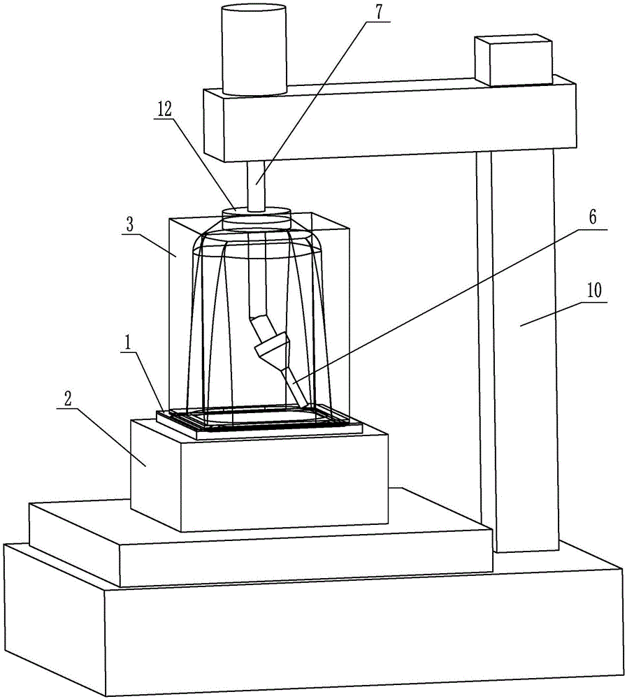
[0032] Specific implementation mode three: combination image 3 , Figure 4 , Figure 6 and Figure 7 Explain that the pressure medium cavity 3 adopted in the second step of this embodiment is a composite structure of the rigid constraining frame 8 and the flexible bladder 9, and the lower end of the rigid constraining frame 8 uses a pressing block 13 to press the lower edge of the flexible bladder 9 against the surface to be cut. On the processed blank 1, the upper part of the flexible bag 9 is sealed between the sealing ring 12 and the actuator 7, so that a pressure medium cavity is formed between the flexible bag 9 and the blank 1 to be cut.
[0033] The pressure medium cavity 3 used in step 2 is a composite structure of the rigid constraint frame 8 and the flexible capsule 9, and the lower end of the rigid constraint frame 8 presses the lower edge of the flexible capsule 9 against the blank 1 to be cut, so that the flexible capsule 9 A pressure medium cavity is formed b...
PUM
 Abstract
Description
Claims
Application Information
 - R&D
- Intellectual Property
- Life Sciences
- Materials
- Tech Scout
- Unparalleled Data Quality
- Higher Quality Content
- 60% Fewer Hallucinations
Browse by: Latest US Patents, China's latest patents, Technical Efficacy Thesaurus, Application Domain, Technology Topic, Popular Technical Reports.
© 2025 PatSnap. All rights reserved.Legal|Privacy policy|Modern Slavery Act Transparency Statement|Sitemap|About US| Contact US: help@patsnap.com


