Magnetic Saturation Feedback Fluxgate Sensor
A fluxgate sensor and state feedback technology, which is applied to the magnetic field measurement and the size/direction of the magnetic field using the principle of magnetic flux control. It can solve the problems of complex probes and detection circuits, poor performance indicators, etc. , the effect of easy processing and simplified circuit structure
- Summary
- Abstract
- Description
- Claims
- Application Information
AI Technical Summary
Problems solved by technology
Method used
Image
Examples
Embodiment 1
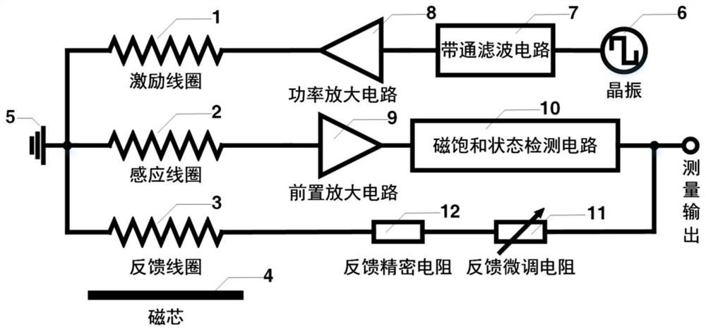
[0062] In order to realize the miniaturization and low-cost design of the sensor, the magnetic saturation state detection circuit 10 of the magnetic saturation state feedback type fluxgate sensor can be composed of a hysteresis comparison circuit 17 and an integration circuit 18 . After the induction signal output signal is amplified by the preamplifier circuit 9, it is converted into a rectangular wave signal by the hysteresis comparison circuit 17, and the corresponding magnetic induction intensity is calculated and output by the integration circuit 18, and then the output terminal passes through the feedback fine-tuning resistor 11, feedback The precision resistor 12 is connected with the feedback coil. When the sensor system reaches the feedback balance, the hysteresis comparator circuit 17 outputs a rectangular wave signal with a duty cycle close to 50%, and the output of the integrating circuit represents the magnetic field detection output.
[0063] Specifically, the pr...
Embodiment 2
[0067] On the premise of realizing miniaturization and low cost, in order to realize the high sensitivity and low noise design of the sensor, the magnetic saturation state detection circuit 10 of the magnetic saturation state feedback type fluxgate sensor needs to be composed of a hysteresis comparison circuit 17 and a low-pass filter circuit. 19. An amplifier circuit 20 and an integrating circuit 18 are formed. After the induction signal output signal is amplified by the preamplifier circuit 9, it is converted into a rectangular wave signal by the hysteresis comparison circuit 17, and the low-pass filter circuit 19 extracts the DC component in the rectangular wave signal, and the amplifying circuit 20 is used to improve the feedback link. The integration circuit 18 is connected to the feedback coil via the feedback fine-tuning resistor 11 and the feedback precision resistor 12 to form a feedback link. When the sensor system reaches the feedback balance, the output of the inte...
PUM
 Abstract
Description
Claims
Application Information
 - R&D
- Intellectual Property
- Life Sciences
- Materials
- Tech Scout
- Unparalleled Data Quality
- Higher Quality Content
- 60% Fewer Hallucinations
Browse by: Latest US Patents, China's latest patents, Technical Efficacy Thesaurus, Application Domain, Technology Topic, Popular Technical Reports.
© 2025 PatSnap. All rights reserved.Legal|Privacy policy|Modern Slavery Act Transparency Statement|Sitemap|About US| Contact US: help@patsnap.com


