Stepped sealing structure of optical cable connector box

A technology of optical cable joint box and sealing structure, which is applied in the direction of fiber mechanical structure, light guide, optics, etc., can solve the problems of insufficient temperature cycle performance, high construction operation requirements, and poor sealing performance, so as to reduce product operation risks, The product has a wide range of adaptability and the effect of increasing the sealing stability

Inactive Publication Date: 2018-12-11
胡肖平
View PDF0 Cites 4 Cited by
  • Summary
  • Abstract
  • Description
  • Claims
  • Application Information

AI Technical Summary

Problems solved by technology

Most of the existing optical cable splice boxes are sealed with non-vulcanized rubber, and non-vulcanized rubber needs to be added again for repeated use. The cost of repeated use is high and it is inconvenient to use
The fiber optic cable splice box sealed with vulcanized rubber is easy to reuse, but the temperature cycle performance cannot meet the requirements (national standard: Y / DT814-2007)
The failure to meet the performance requirements mainly has the following reasons: the vulcanized rubber seal seals the box body and the cable at the same time, which requires high construction operations and poor stability; the thermal expansion coefficient of the existing vulcanized rubber is relatively large, and the compression set is relatively large. Large, after the low temperature test, the volume will shrink accordingly, and the rebound performance will decrease at low temperature, which is an important reason for its poor sealing performance

Method used


Image

  • Stepped sealing structure of optical cable connector box
  • Stepped sealing structure of optical cable connector box
  • Stepped sealing structure of optical cable connector box

Examples


Embodiment 1

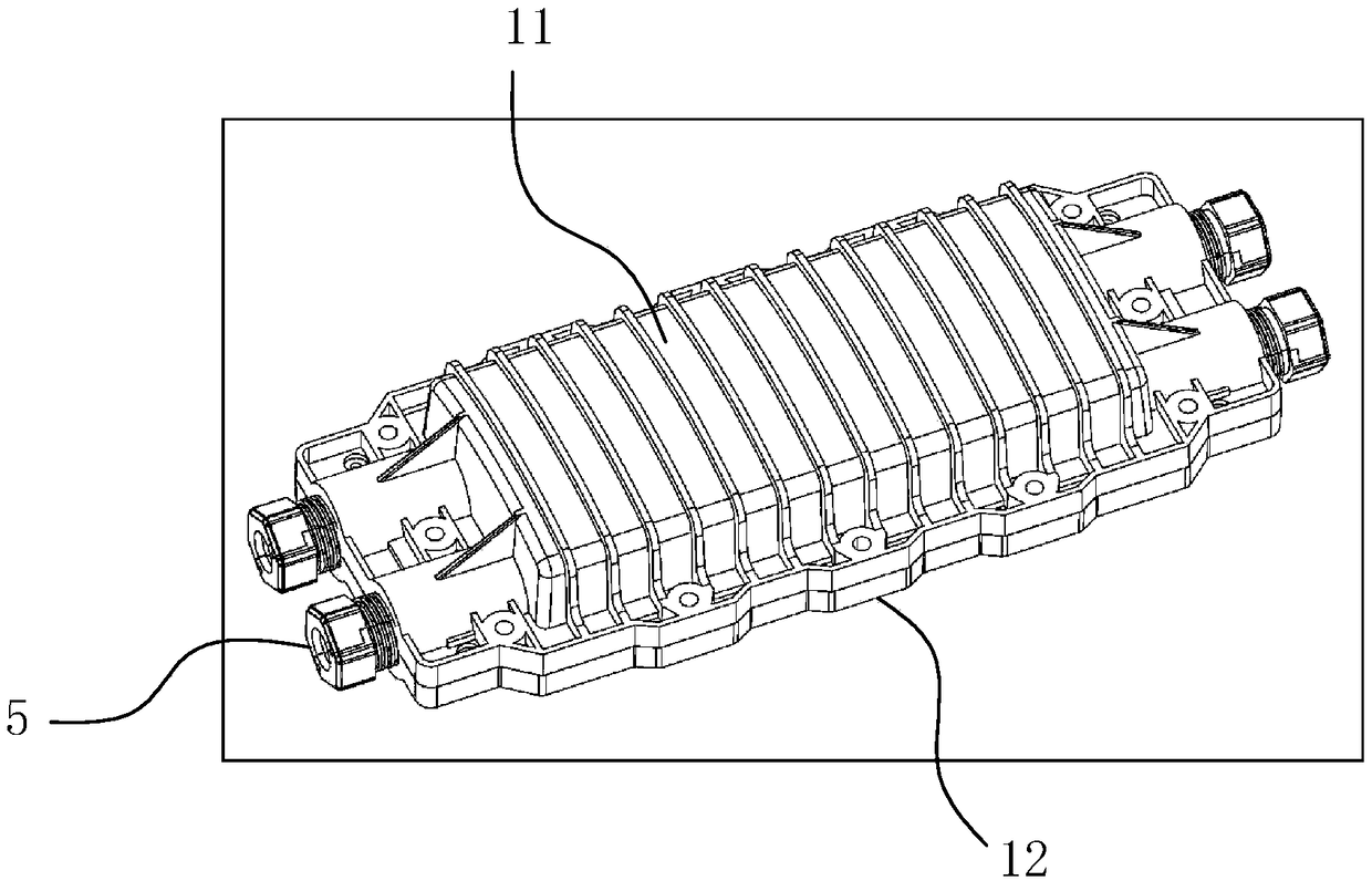
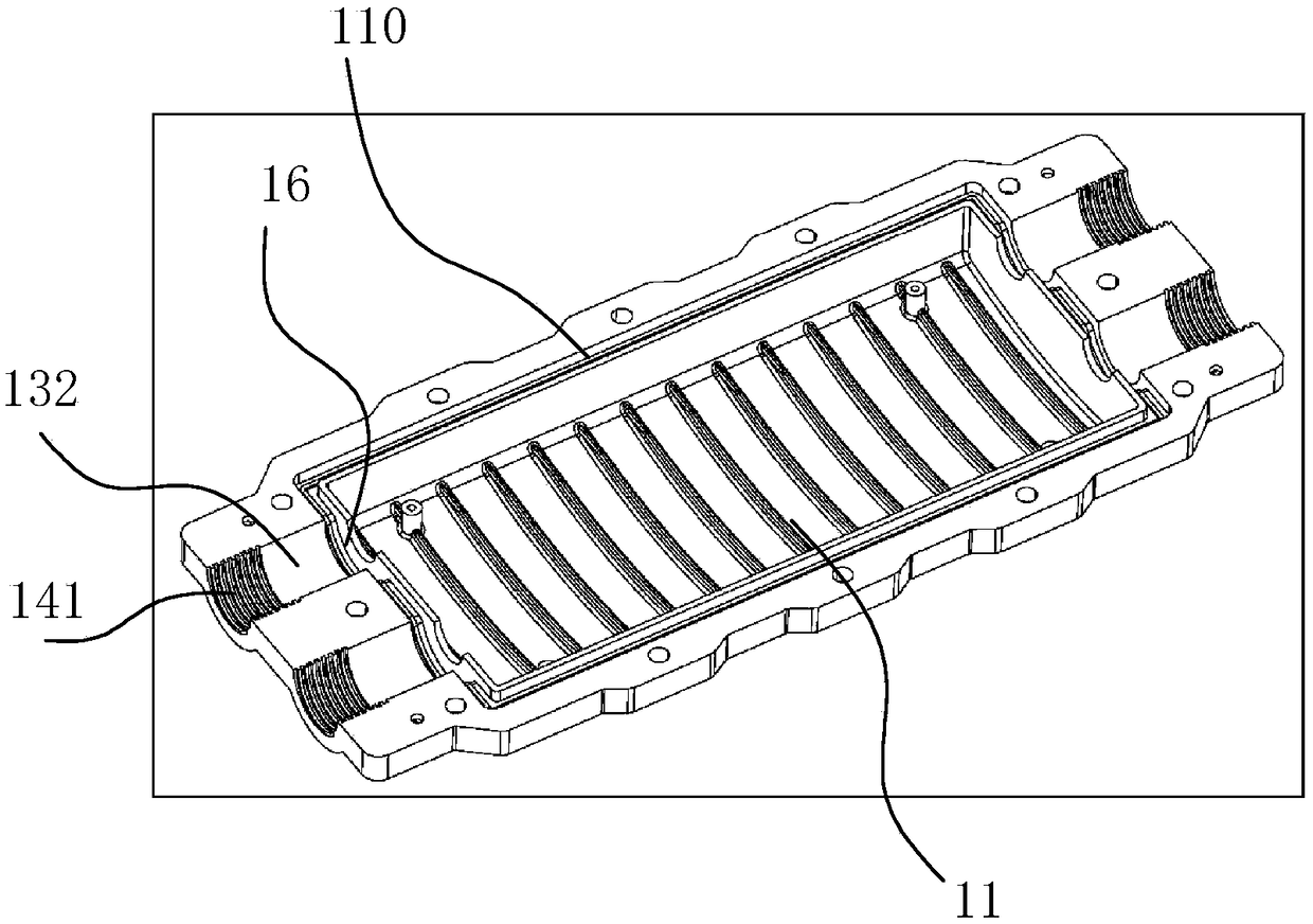
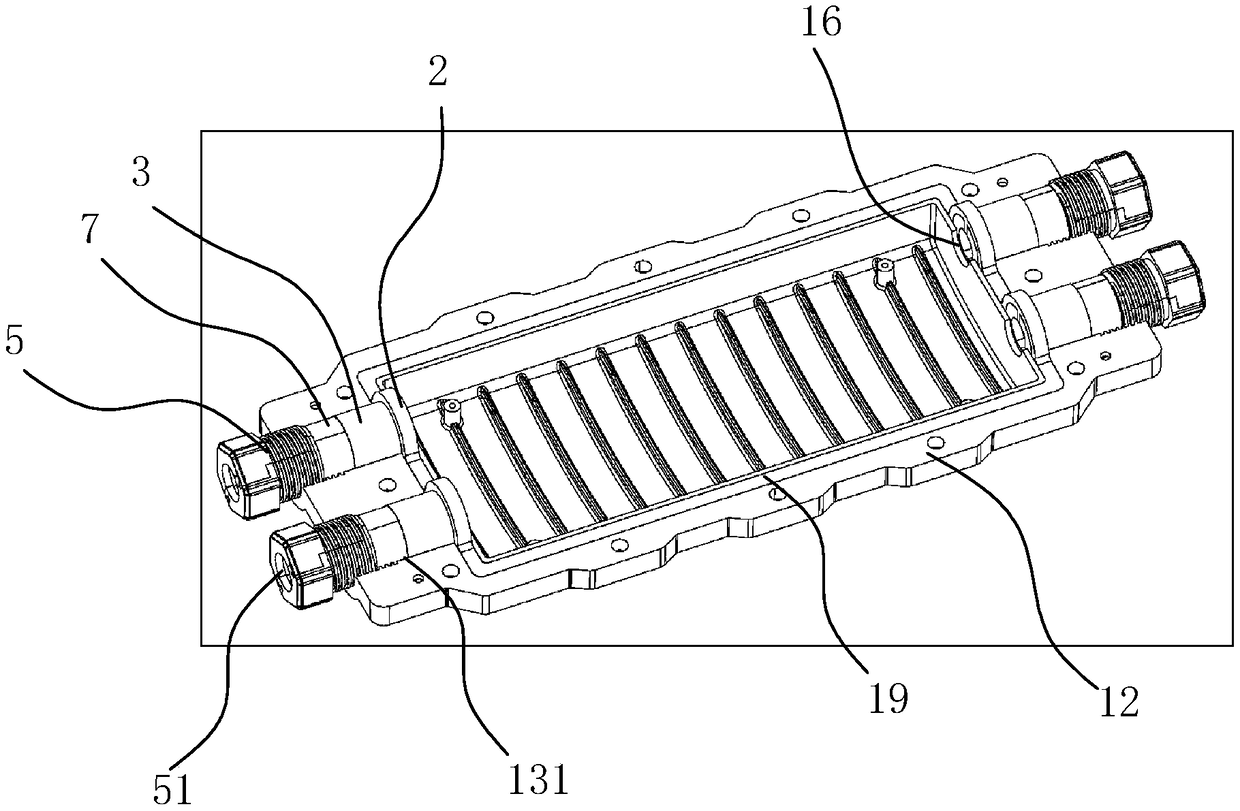
[0071] see Figure 1-Figure 10 , the step-by-step sealing structure of the optical cable splice box in this embodiment includes an upper box body 11 and a lower box body 12, the optical cable splice box has an optical cable embedding hole for passing through the optical cable, and the optical cable embedding hole is from the inside to the outside A retaining ring 2, an elastic sealing ring 3, an extruded module and an extruded part are arranged in sequence, and the retaining ring 2, the elastic sealing ring, the extruded module 7 and the extruded part all have perforations for passing through the optical cable, and the retaining ring 2 is fixed At the inner end of the fiber optic cable embedding hole, the extruding piece is pressed against one end of the extrusion module 7, and the other end of the extrusion module 7 is abutted against one end of the elastic sealing ring 3, and the function of the extrusion piece is to longitudinally squeeze the elastic seal ring, so that the ...

Embodiment 2

[0083] see Figure 11-Figure 23 , the step-by-step sealing structure of the optical cable splice box in this embodiment includes an upper box body 11 and a lower box body 12, the optical cable splice box has an optical cable embedding hole for passing through the optical cable, and the optical cable embedding hole is from the inside to the outside A retaining ring 2, an elastic sealing ring 3, an extruded module 7 and an extruded part are arranged in sequence, and the retaining ring 2, the elastic sealing ring, the extruded module 7 and the extruded part all have perforations for passing through the optical cable, and the retaining ring 2 It is fixed at the inner end of the optical cable embedding hole, the extruding part is against one end of the extruding module 7, and the other end of the extruding module 7 is against one end of the elastic sealing ring 3, and the function of the extruding part is to longitudinally squeeze the elastic The sealing ring makes the elastic seal...

Embodiment 3

[0096] see Figure 24-Figure 34 , the step-by-step sealing structure of the optical cable splice box in this embodiment includes an upper box body 11 and a lower box body 12, the optical cable splice box has an optical cable embedding hole for passing through the optical cable, and the optical cable embedding hole is from the inside to the outside A retaining ring 2, an elastic sealing ring 3, an extruded module 7 and an extruded part are arranged in sequence, and the retaining ring 2, the elastic sealing ring, the extruded module 7 and the extruded part all have perforations for passing through the optical cable, and the retaining ring 2 It is fixed at the inner end of the optical cable embedding hole, the extruding part is against one end of the extruding module 7, and the other end of the extruding module 7 is against one end of the elastic sealing ring 3, and the function of the extruding part is to longitudinally squeeze the elastic The sealing ring makes the elastic seal...


PUM


Abstract

The invention discloses a stepped sealing structure of an optical cable connector box. The stepped sealing structure is characterized in that the stepped sealing structure comprises an upper box bodyand a lower box body, the optical cable connector box is provided with an optical cable embedding hole used for allowing an optical cable to penetrate through, the optical cable embedding hole is provided with a retaining ring, an elastic sealing ring and an extrusion member arranged in sequence from the inside to the outside, the retaining ring, the elastic sealing ring and the extrusion member each comprise a penetrating hole used for allowing the optical cable to penetrate through, the retaining ring is fixed in the inner end of the optical cable embedding hole, an end portion of the elastic sealing ring is abutted against the retaining ring, and the retaining ring is formed by a hard inner core and an elastic sealing peripheral member arranged at the periphery of the hard inner core. According to the stepped sealing structure, an area of the optical cable embedding hole of the optical cable connector box adopts stepped sealing, the sealing of the optical cable embedding hole is realized through the elastic sealing ring, the sealing between the upper box body and the lower box body is realized through the elastic sealing peripheral member of the retaining ring, and the sealing structure is more reliable.

Description

technical field [0001] The invention relates to a step-by-step sealing structure of an optical cable joint box. Background technique [0002] The optical cable splice box is used for the connection and protection between optical cables on the optical fiber network. In the prior art, in order to meet the needs of the straight-through and divergent connection functions of the optical cable splice box, the upper and lower covers of the box body and the sealing strips must be designed as a Hafur-type sealing structure that can be opened and fixed at the top and bottom. The optical cable buried hole of the existing optical cable splice box is usually sealed by a soft sealing material such as silicone rubber, so as to ensure good airtightness and waterproof performance, thereby avoiding moisture erosion. Most of the existing optical cable splice boxes are sealed with non-vulcanized rubber, and non-vulcanized rubber needs to be added again for repeated use, which is costly and inc...

Claims


Application Information

Patent Timeline
Patent Type & Authority Applications(China)
IPC IPC(8): G02B6/44
CPCG02B6/4446
Inventor 胡肖平
Owner 胡肖平
Why Eureka
Try Eureka