A pneumatic self-cleaning keyboard

Active Publication Date: 2018-12-11
SHENZHEN TORICH ELECTRONICS TECH CO LTD
View PDF4 Cites 8 Cited by
  • Summary
  • Abstract
  • Description
  • Claims
  • Application Information

AI Technical Summary

Problems solved by technology

[0002] The keyboard is a common computer accessory for inputting information. During use, users need to tap the keycaps of the keyboard with their fingers to perform input operations. Because human fingertips will secrete sweat and grease, and many urban White-collar workers sit in front of the computer for three meals a day, and do not have the habit of washing their hands before typing on the keyboard, resulting in more stains on the keyboard, which not only affects the user experience, but also easily breeds bacteria, increasing the risk of illness for users
[0003] However, the current way to clean the keyboard is generally to wipe it with a cloth dipped in water. , the frequency of use of each button is also different, and the targeted cleaning of the buttons cannot be achieved during cleaning

Method used


Image

  • A pneumatic self-cleaning keyboard
  • A pneumatic self-cleaning keyboard
  • A pneumatic self-cleaning keyboard

Examples


Embodiment 1

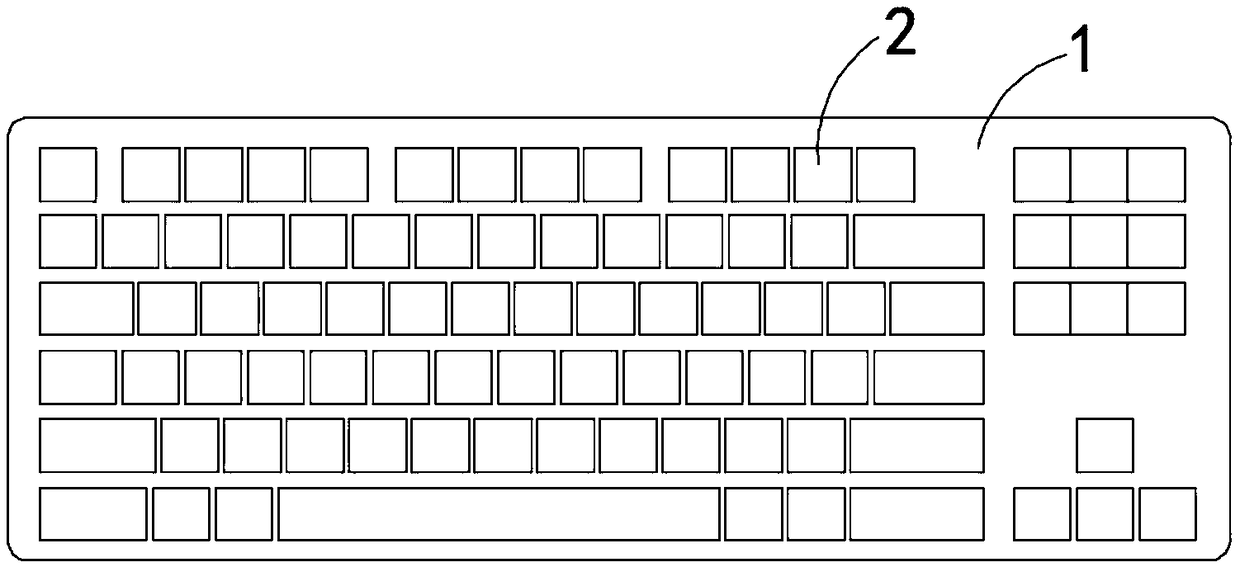
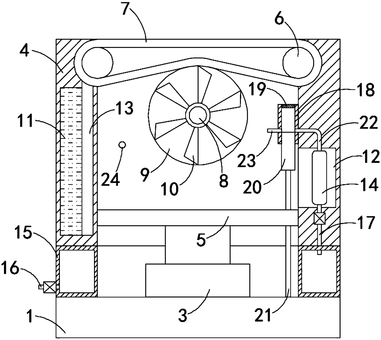
[0019] Such as Figure 1-3 As shown, a pneumatic self-cleaning keyboard includes a base plate 1 and a plurality of keys 2 installed on the base plate 1, the keys 2 include a trigger 3 and a keycap 4, the lower end of the trigger 3 is fixedly connected to the upper end of the base 1, The inner connection plate 5 is fixedly connected to the keycap 4, and the lower end of the connection plate 5 is fixedly connected to the upper end of the trigger 3. When the trigger 3 is pressed, a trigger signal will be sent. Since this is the prior art in the field of keyboards, it is not To go into too much detail, there are two left and right rotating rollers 6 that are rotatably connected in the keycap 4, and the two rotating rollers 6 are connected in rotation through a rotating belt 7. The upper end of the keycap 4 is provided with an opening that matches the rotating belt 7. The upper surface of 7 is flush with the upper surface of keycap 4, and keycap 4 is rotatably connected with rotati...

Embodiment 2

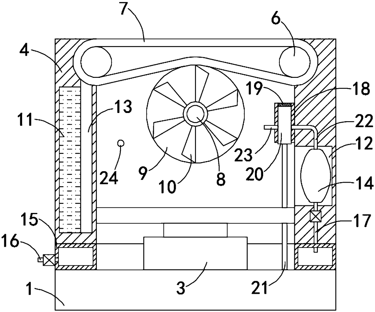
[0024] Such as Figure 4 As shown, the difference between this embodiment and Embodiment 1 is that: the exhaust hole 24 is arranged close to the lower surface of the rotating belt 7 .

[0025] In this embodiment, the exhaust hole is arranged close to the lower surface of the rotating belt 7. When the gas is discharged from the exhaust hole 24, the volatilization of the cleaning liquid on the surface of the rotating belt 7 can be intensified, which is especially suitable for game players and avoids knocking. The frequency is too high, resulting in the situation that the cleaning liquid on the surface of the rotating belt 7 has no time to volatilize.


PUM


Abstract

The invention belongs to the field of computer accessories, in particular to a pneumatic self-cleaning keyboard, which includes a base plate and a plurality of keys mounted on the base plate. Each keyincludes a trigger and a key cap, the lower end of the trigger is fixedly connected with the upper end of the bottom plate, the key cap is internally fixedly connected with a connecting plate, the lower end of the connecting plate is fixedly connected with the upper end of the trigger, each key cap is rotatably connected with left and right rotating rollers, between the two rotate rollers are rotatably connected by a rotating belt, the upper end of the key cap is provided with an opening matched with the rotating belt, the upper surface of the rotating belt is flush with the upper surface ofthe key cap, the key cap is rotatably connected with a rotating shaft, a friction wheel and a wind wheel are fixedly connected coaxially on the rotating shaft, two side walls of the key cap are provided with a liquid-containing chamber and a placing groove respectively, and the liquid-containing chamber is filled with cleaning liquid. The rotating belt can automatically rotate and be cleaned by awater absorbing plate in the use process, the upper surface of the rotating belt can be kept clean, and the self-cleaning function of the keyboard can be realized.

Description

technical field [0001] The invention belongs to the field of computer accessories, in particular to a pneumatic self-cleaning keyboard. Background technique [0002] The keyboard is a common computer accessory for inputting information. During use, users need to tap the keycaps of the keyboard with their fingers to perform input operations. Because human fingertips will secrete sweat and grease, and many urban White-collar workers sit in front of the computer for three meals a day, and do not have the habit of washing their hands before typing on the keyboard, resulting in more stains on the keyboard, which not only affects the user experience, but also easily breeds bacteria, increasing the risk of illness for users . [0003] However, the current way to clean the keyboard is generally to wipe it with a cloth dipped in water. , the frequency of use of each button is also different, and it is impossible to achieve targeted cleaning of the buttons during cleaning. [0004]...

Claims


Application Information

Patent Timeline
Patent Type & Authority Applications(China)
IPC IPC(8): G06F3/02
CPCG06F3/0202G06F3/0227
Inventor 王清玉
Owner SHENZHEN TORICH ELECTRONICS TECH CO LTD
Why Eureka
Try Eureka