Ultrasonic atomization device and electronic cigarette

An atomizing device and ultrasonic technology, applied in the direction of tobacco, smoker's products, applications, etc., can solve the problems of endangering the health of users, unable to discharge e-liquid in time, damage to users' health, etc., and achieve the effect of reducing waste.

Inactive Publication Date: 2018-10-09
深圳市量子激光科技有限公司
View PDF0 Cites 8 Cited by
  • Summary
  • Abstract
  • Description
  • Claims
  • Application Information

AI Technical Summary

Problems solved by technology

[0002] Most of the e-cigarettes on the market use evaporating components or heating devices to heat the e-liquid from liquid to mist, but the use of these structures will cause the e-liquid to produce chemical reactions and produce toxic substances, which have a certain impact on the health of users. With the development of the times, an ultrasonic atomization device has gradually begun to be used in the field of electronic cigarettes, using ultrasonic high-frequency vibration to ultrasonically atomize the e-liquid next to the ultrasonic device, because ultrasonic atomization is a physical process , all e-liquids will not generate toxic and harmful substances, but there are the following problems with this technology:
[0003] 1) The unused e-liquid in the atomization chamber cannot be discharged in time, which may easily cause residue of e-liquid; resulting in the deterioration of the e-liquid in the atomization chamber after a long time, endangering the health of users;

Method used


Image

  • Ultrasonic atomization device and electronic cigarette
  • Ultrasonic atomization device and electronic cigarette
  • Ultrasonic atomization device and electronic cigarette

Examples


Embodiment Construction

[0036] In order to express the present invention more clearly, the present invention will be further described below with reference to the accompanying drawings.

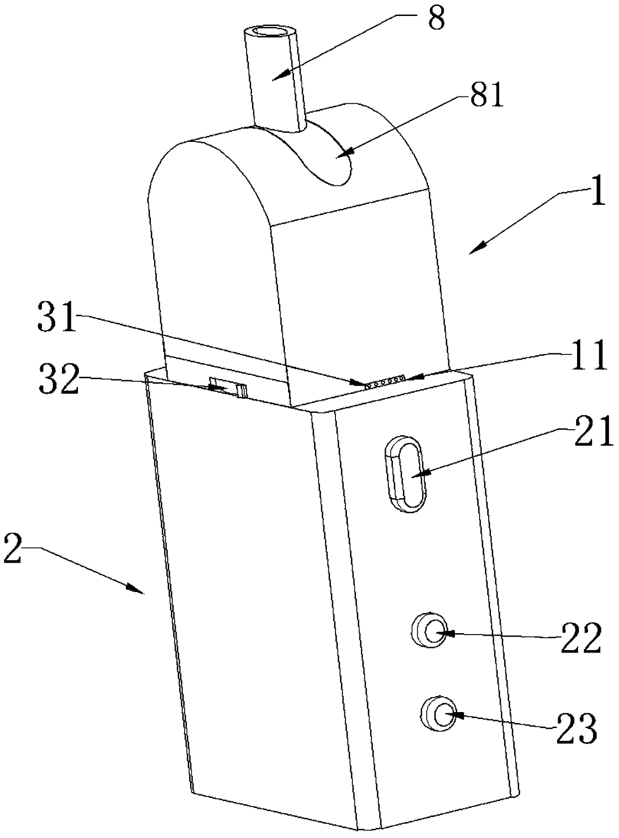
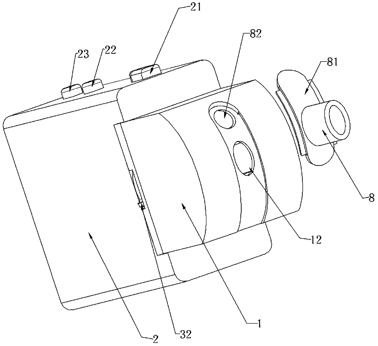
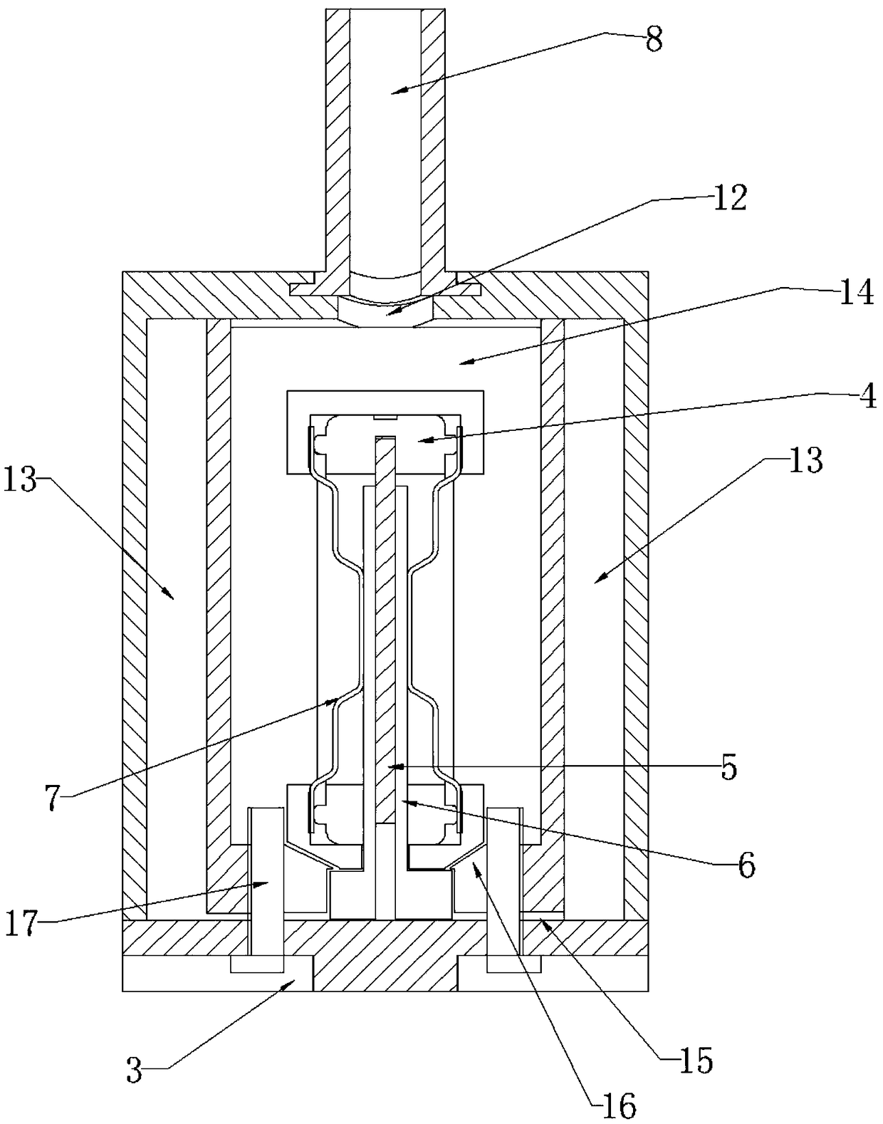
[0037] See figure 1 with figure 2 , The present invention provides an ultrasonic atomization device, including a smoke generating device 1 and a driving device 2. The smoke generating device 1 is electrically connected to the driving device 2, and the smoke generating device 1 includes an ultrasonic transducer assembly 5, a smoke oil cavity 13 and a mist The atomization cavity 14 is provided with a channel 15 connected to the e-liquid cavity 13. The atomization cavity 14 is provided with an ultrasonic transducer assembly 5, and one end of the ultrasonic transducer assembly 5 is electrically connected to the driving device 2. The outer side of the transducer assembly 5 is provided with an oil-conducting layer 6. The oil-conducting layer 6 is in contact with the e-liquid cavity 13 through the channel 15. The atomization ...


PUM


Abstract

The invention discloses an ultrasonic atomization device and an electronic cigarette. The ultrasonic atomization device comprises a smoke generation device and a driving device, wherein the smoke generation device is electrically connected with the driving device; the smoke generation device comprises an ultrasonic transduction component, an atomization cavity and a tobacco tar cavity; a through hole connected with tobacco tar is formed in the atomization cavity; the atomization cavity is internally provided with the ultrasonic transduction component; one end of the ultrasonic transduction component is eclectically connected with the driving device; the other end of the ultrasonic transduction component is arranged inside the atomization cavity; a tobacco tar guide layer is adhered to theouter side of the ultrasonic transduction component; the tobacco tar guide layer is in contact with the tobacco tar cavity through the through hole; a backflow channel is formed in the lower part of the atomization cavity; one end of the backflow channel is communicated with the interior of the atomization cavity; the other end of the backflow channel is connected with the tobacco tar guide layer.The ultrasonic atomization device is simple in structure, the atomization cavity can be effectively kept clean without tobacco tar residue, and the service life of the smoke generation device can beeffectively prolonged.

Description

Technical field [0001] The invention relates to the field of atomization devices, in particular to an ultrasonic atomization device and an electronic cigarette. Background technique [0002] Most of the e-cigarettes on the market use evaporation components or heating devices to heat the e-liquid from liquid to mist, but the use of these structures will cause the e-liquid to produce chemical reactions and produce toxic substances, which has a certain effect on the health of users. With the development of the times, an ultrasonic atomization device has gradually begun to be used in the field of electronic cigarettes. The high-frequency vibration of ultrasonic waves is used to ultrasonically atomize the smoke oil located next to the ultrasonic device, because ultrasonic atomization is a physical process , All smoke oil will not generate toxic and harmful substances, but there are the following problems with this technology: [0003] 1) The unused e-liquid in the atomization cavity ca...

Claims


Application Information

Patent Timeline
Patent Type & Authority Applications(China)
IPC IPC(8): A24F47/00
CPCA24F47/008
Inventor 杨作权
Owner 深圳市量子激光科技有限公司
Why Eureka
Try Eureka