Rotor magnetic steel

A magnetic steel and rotor technology, applied in the direction of magnetic circuit, magnetic circuit rotating parts, magnetic circuit shape/style/structure, etc., can solve the problems of motor failure, low efficiency of magnetic tile installation, increased labor intensity of workers, etc., to achieve Improve installation efficiency and facilitate operation

Pending Publication Date: 2018-12-11
ANHUI TONGHUA NEW ENERGY POWER
View PDF0 Cites 0 Cited by
  • Summary
  • Abstract
  • Description
  • Claims
  • Application Information

AI Technical Summary

Problems solved by technology

[0003] Among them, in the bonding process between the magnetic tile and the motor, the glue is generally applied on the inner surface of the magnetic tile first, and then attached to the surface of the rotor core. Due to the magnetic force between the magnetic tile and the rotor core and the two magnetic The magnetic force between the tiles, so after the magnetic tiles are attached to the rotor core, it needs to be manually pressed until the glue initially bonds the magnetic tiles to the rotor core, so that the installation efficiency of the magnetic tiles is low, and the labor intensity of the workers is increased; In addition, The N pole and S pole of the magnetic tile need to be arranged by the worker after distinguishing. Once the magnetic tile is arranged in the wrong direction, the motor will not be able to run

Method used


Image

  • Rotor magnetic steel
  • Rotor magnetic steel
  • Rotor magnetic steel

Examples


Embodiment Construction

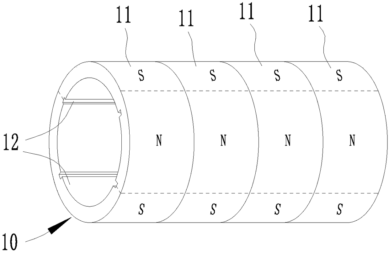
[0011] A rotor magnet, comprising an annular magnet unit 11 , at least two axial end surfaces of the magnet unit 11 are arranged in close contact with each other to form a tubular magnet body 10 .

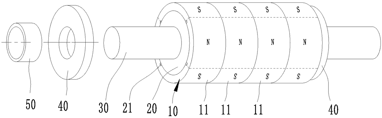
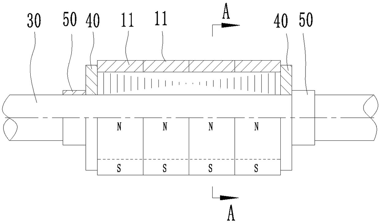
[0012] The worker directly sets the ring-shaped magnetic steel unit 11 onto the rotor core 20 in turn, which is convenient for the worker to operate and improves the installation efficiency of the magnetic steel body 10. The application can arrange a corresponding number of magnetic steel units according to the different axial lengths of the rotor core 20. The magnetic steel unit does not need additional design and manufacture of magnetic steel. In addition, the magnetic steel body cannot fall off even on high-speed motors.

[0013] In order to effectively limit the circumferential rotation of the magnetic steel unit 11, a limiting groove 12 is provided on the inner wall of the annular magnetic steel unit 11, and the groove length direction of the limiting groove 12 is consistent w...


PUM


Abstract

A magnet steel for rotor is composed of annular magnet steel unit, and at least two axial end faces of the magnet steel unit are arranged in close contact with each other to form a tubular magnet steel body. Thus, the annular magnetic steel unit can be directly sleeved on the rotor core in turn for the worker to conveniently operate, and to improve the installation efficiency of the magnetic steel body. The invention can arrange a corresponding number of magnetic steel units accord to different axial lengths of the rotor core, and does not require additional design and manufacture of the magnetic steel. In addition, even in a high-speed motor, the magnetic steel body can not fall off.

Description

technical field [0001] The invention relates to the technical field of motors, in particular to a magnetic steel constituting a motor rotor. Background technique [0002] At present, the rotor magnets of permanent magnet synchronous motors are generally in the shape of tiles. This kind of magnets is also called magnetic tiles. The magnetic tiles are usually glued to the outer surface of the rotor core one by one with glue. The magnetic tiles on the general low-speed motor This arrangement can be used, but the high-speed motor needs to be additionally covered with a ring-shaped magnetic tile sleeve after bonding to prevent the magnetic tile from falling off during use. [0003] Among them, in the bonding process of the magnetic tile and the motor, the glue is generally applied on the inner surface of the magnetic tile first, and then attached to the surface of the rotor core. Due to the magnetic force between the magnetic tile and the rotor core and the two magnetic The magn...

Claims


Application Information

Patent Timeline
IPC IPC(8): H02K1/06H02K1/27
CPCH02K1/06H02K1/278
Inventor 丁洁管华饶启明赵云峰文明欧阳山
Owner ANHUI TONGHUA NEW ENERGY POWER
Why Eureka
Try Eureka