
Oven

A technology for ovens and cabinets, which is applied in the field of ovens, and can solve problems such as difficult installation of rotating shafts and influence on transmission stability, and achieve the effects of stable transmission structure, convenient installation or disassembly, and convenient installation and transmission

Active Publication Date: 2018-12-14
佛山市德嶸电器有限公司
View PDF6 Cites 3 Cited by
  • Summary
  • Abstract
  • Description
  • Claims
  • Application Information

AI Technical Summary

Problems solved by technology

[0002] Ovens are common household appliances. Many kinds of food are suitable for baking. They can emit wonderful fragrances through baking. In order to make these foods evenly baked, the food can be rotated in the oven so that the outer surfaces of the food All can be baked evenly. In the prior art, there are ovens with manual and electric control of rotation, which have a rotating body for placing food. The rotating shaft needs to be set as a split detachable structure, so it is inevitable to install a coupling to transmit the power of the manual device or the motor shaft to the rotating shaft. It is difficult to install the existing product rotating shaft into the coupling. By changing the shape of the coupling, the shaft can be easily loaded into the coupling, but it has a greater impact on the stability of the transmission; in the prior art, there is no structure for adding a clutch device to the coupling to allow the shaft to be easily loaded

Method used


Image

  • Oven
  • Oven
  • Oven

Examples


Embodiment Construction

[0025] An oven of the present invention is described with reference to the accompanying drawings.

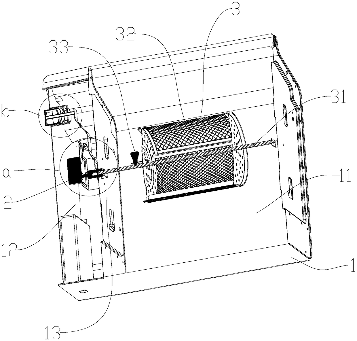
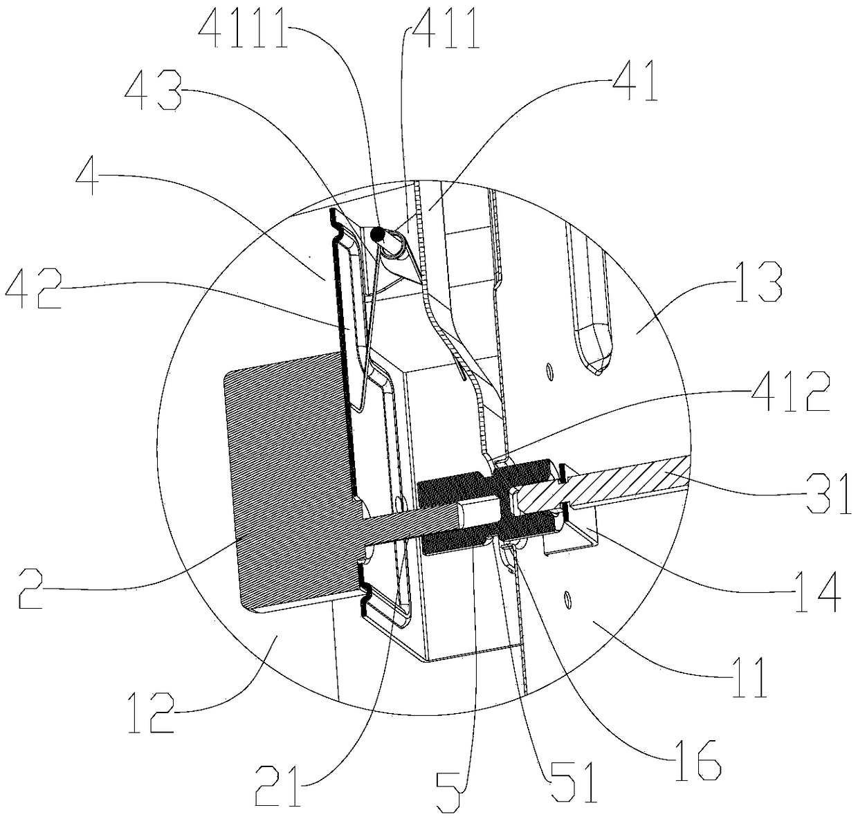
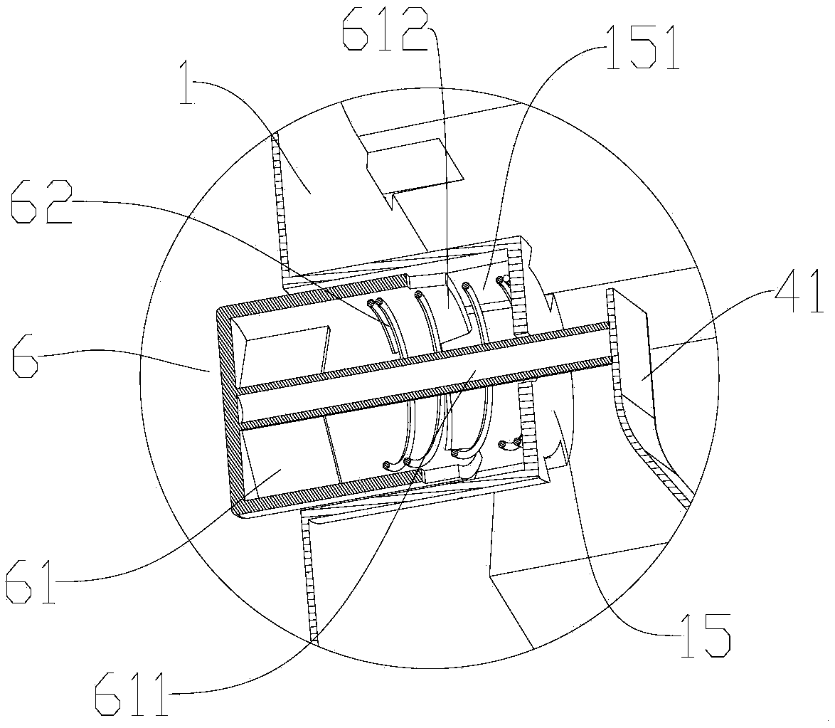
[0026] Such as figure 1 The shown oven includes a box body 1 of the oven, a motor 2 and a rotating body 3 with a rotating shaft 31. The rotating shaft 31 rotates so that the rotating body 3 rotates around the axis of the rotating shaft 31. The box body 1 forms at least a second A cavity 11 and a second cavity 12, the first cavity 11 and the second cavity 12 are separated by a partition plate 13, the first cavity 11 is used as the heating cavity of the oven, food will be heated and baked in the first cavity 11 system, the rotating body 3 is accommodated in the first cavity 11, the rotating body 3 is used as a food carrying device, and the partition plate 13 is fixed with a bracket 14 for the rotating body 3 to be installed; The second bracket can also be set on the side panel for the installation of the rotating body 3, and the rotating body 3 can be better supported in the firs...


PUM


Abstract

The invention discloses an oven, including a box of the oven, a motor, and a rotor with a rotating shaft. The rotating shaft rotates, so the rotor rotates around an axis of the rotating shaft. The boxis at least provided with a first cavity and a second cavity. The first cavity and the second cavity are separated by a separating plate. The rotor is held in the first cavity. The separating plate is fixedly provided with a support for mounting the rotor. The rotor is arranged in the support along a direction intersecting with the axis of the rotating shaft. The motor is arranged in the second cavity. The motor has a motor shaft. The motor shaft is corresponding to the rotating shaft, and the separating plate is provided with a through hole used for connecting the motor shaft and the rotating shaft on the corresponding position. The oven also comprises a coupling connecting the motor shaft and the rotating shaft, and a clutch device controlling motions of the coupling. The clutch deviceis arranged in the second cavity. The clutch device moves the coupling, to provide convenience for installation of the rotating shaft, and the clutch device and the coupling transmit in a cooperated manner. The clutch device is added in the oven, providing convenience for mounting and dismounting of the rotating shaft.

Description

technical field [0001] The invention relates to the field of electric cooking devices, in particular to an oven. Background technique [0002] Ovens are common household appliances. Many kinds of food are suitable for baking. They can emit wonderful fragrances through baking. In order to make these foods evenly baked, the food can be rotated in the oven so that the outer surfaces of the food All can be baked evenly. In the prior art, there are ovens with manual and electric control of rotation, which have a rotating body for placing food. The rotating shaft needs to be set as a split detachable structure, so it is inevitable to install a coupling to transmit the power of the manual device or the motor shaft to the rotating shaft. It is difficult to install the existing product rotating shaft into the coupling. By changing the shape of the coupling, the shaft can be easily loaded into the coupling, but it has a greater impact on the stability of the transmission; in the prio...

Claims


Application Information

Patent Timeline
IPC IPC(8): A47J37/06A47J37/04
CPCA47J37/04A47J37/0629
Inventor 高孝会
Owner 佛山市德嶸电器有限公司
Learn More