High temperature liquid emergency discharge tank buffer structure
A technology of emergency discharge and buffer structure, applied in the field of buffer structure, can solve problems such as large thermal stress, equipment danger, explosion, etc., and achieve the effect of reducing stress
- Summary
- Abstract
- Description
- Claims
- Application Information
AI Technical Summary
Problems solved by technology
Method used
Image
Examples
Embodiment Construction
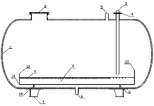
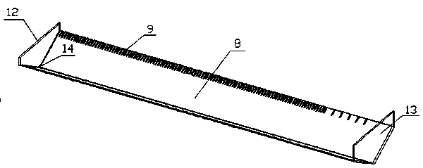
[0014] Specific embodiments of the present invention will be described in detail below in conjunction with the accompanying drawings. according to figure 1 The structure shown includes tank body 1, manhole 2, liquid inlet 3, inlet flange 4, gas pressure relief port 5, liquid outlet 6, support 7, buffer tank 8, buffer tank side plate opening 9, buffer tank Support plate 10, buffer tank support plate 11, buffer tank left baffle plate 12, buffer tank right baffle plate 13, buffer tank left bottom opening 14. Such as figure 2 As shown, the thickness of the buffer tank is 8mm~15mm, the V-shaped angle range of the buffer tank is 100゜~150゜, and the buffer tank 8 is set under the inlet pipe. When the high-temperature liquid enters the buffer tank 8 through the inlet pipe, the high-temperature liquid enters the buffer tank 8 has a certain speed. In order to prevent splashing, baffles are set at both ends of the buffer tank 8. The left baffle 13 of the buffer tank is 100mm~150mm high...
PUM
 Abstract
Description
Claims
Application Information
 - R&D
- Intellectual Property
- Life Sciences
- Materials
- Tech Scout
- Unparalleled Data Quality
- Higher Quality Content
- 60% Fewer Hallucinations
Browse by: Latest US Patents, China's latest patents, Technical Efficacy Thesaurus, Application Domain, Technology Topic, Popular Technical Reports.
© 2025 PatSnap. All rights reserved.Legal|Privacy policy|Modern Slavery Act Transparency Statement|Sitemap|About US| Contact US: help@patsnap.com


