Transmission line galloping monitoring method based on OPGW ground wire induced current

A technology for power transmission lines and induced currents, applied in the high voltage field, can solve the problems of complex calculation, short distance and long time required for analyzing video images, and achieve the effect of simple and fast monitoring methods.

Active Publication Date: 2018-12-14
TSINGHUA UNIV
View PDF9 Cites 7 Cited by
  • Summary
  • Abstract
  • Description
  • Claims
  • Application Information

AI Technical Summary

Problems solved by technology

[0003] At present, the galloping of transmission lines is mostly monitored by analyzing live video images of transmission lines. However, the distance that can be monitored by this method is relatively short, and the calculation of analyzing video images is complex and takes a long time.

Method used


Image

  • Transmission line galloping monitoring method based on OPGW ground wire induced current
  • Transmission line galloping monitoring method based on OPGW ground wire induced current
  • Transmission line galloping monitoring method based on OPGW ground wire induced current

Examples


Embodiment

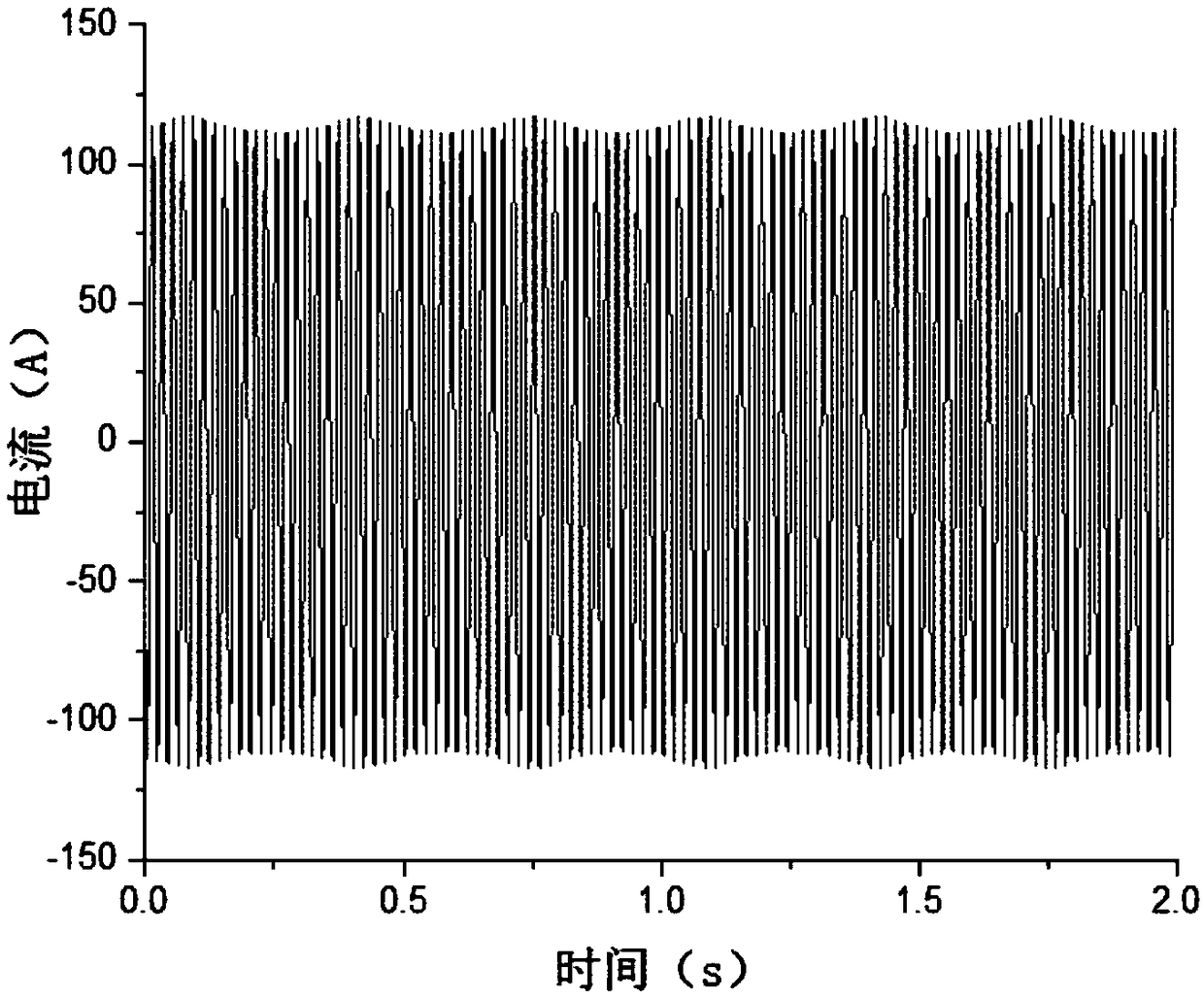
[0049] The conductor danced at the 50th base tower of a 500kV double-circuit transmission line. Wave recorders were installed on five adjacent base towers; At the 55th base tower along the line, the oscilloscope installed on the tower is triggered and records the current waveform, such as image 3 As shown, through effective signal analysis methods, the dancing signal waveform can be obtained as Figure 4 As shown, and according to the coupling coefficient between the OPGW ground wire and the wire, the galloping amplitude is calculated to be 4m, and the galloping frequency is 3Hz. At the same time, the galloping position of the wire can be located by combining the current waveforms recorded by the wave recorders installed at different towers, and the galloping at the 50th base tower can be calculated.

[0050] The advantages of the present invention are:

[0051] 1. The present invention can realize galloping monitoring of transmission lines;

[0052] 2. The monitoring dist...


PUM


Abstract

The invention discloses a transmission line galloping monitoring method based on OPGW ground wire induced current. It is assumed that the galloping frequency, galloping amplitude and galloping position of a transmission line conductor need to be deduced by measuring the induced current on an OPGW ground wire of an N-th base tower of a transmission line. The transmission line galloping monitoring method comprises the following steps that a current transformer is installed on the OPGW ground wire of the N-th base tower, and the output end of the current transformer is connected with wave recorders; the wave recorders are provided with a trigger threshold value, and the wave recorders do not record waveforms when the line works normally; and when the conductor gallops, the OPGW ground wire iscoupled with induced overcurrent, the wave recorders are triggered and record the current waveforms; according to signal analysis and an electromagnetic field theory, the coupling coefficient betweenthe OPGW ground wire and conductor is calculated, so that the galloping frequency and galloping amplitude of the conductor are calculated; and by analyzing the waveforms recorded by the wave recorders installed on different towers, the galloping position is located.

Description

technical field [0001] The invention relates to the field of high-voltage technology, in particular to a method for monitoring galloping of transmission lines based on induced currents of OPGW ground wires, which is used for monitoring galloping of overhead transmission lines. Background technique [0002] Overhead transmission lines will be affected by natural conditions during operation, and many disasters and accidents will occur, and galloping is one of the more serious hazards. Overhead transmission line galloping is a self-excited vibration phenomenon with low frequency (about 0.1-3Hz) and large amplitude (up to 10m or more) generated by the wire under the excitation of wind. The harm caused by galloping is multifaceted. The light ones will cause flashover and tripping, and the severe ones will cause damage to hardware and insulators, wire breakage, wire breakage, tower bolts loosening, falling off, and even tower collapse, leading to major power grid accidents. The l...

Claims


Application Information

Patent Timeline
Patent Type & Authority Applications(China)
IPC IPC(8): G01D21/02
CPCG01D21/02
Inventor 张波再木然·乌斯曼何金良胡军庄池杰曾嵘余占清
Owner TSINGHUA UNIV
Why Eureka
Try Eureka