Shield tunnel surrounding rock deformation advanced monitoring structure and monitoring method

A technology for surrounding rock deformation and shield tunneling, applied in the field of tunnels, can solve the problems of inability to feedback surrounding rock deformation data and low monitoring efficiency, and achieve the effects of being beneficial to data collection, improving service life and reducing wear and tear.

Pending Publication Date: 2020-12-08
POWERCHINA CHENGDU ENG
View PDF0 Cites 2 Cited by
  • Summary
  • Abstract
  • Description
  • Claims
  • Application Information

AI Technical Summary

Problems solved by technology

[0008] The technical problem to be solved by the present invention is that in the existing monitoring devices of shield tunnels, not only the deformation data of the surrounding rocks cannot be fed back better from multiple directions during exca

Method used


Image

  • Shield tunnel surrounding rock deformation advanced monitoring structure and monitoring method
  • Shield tunnel surrounding rock deformation advanced monitoring structure and monitoring method
  • Shield tunnel surrounding rock deformation advanced monitoring structure and monitoring method

Examples


Embodiment 1

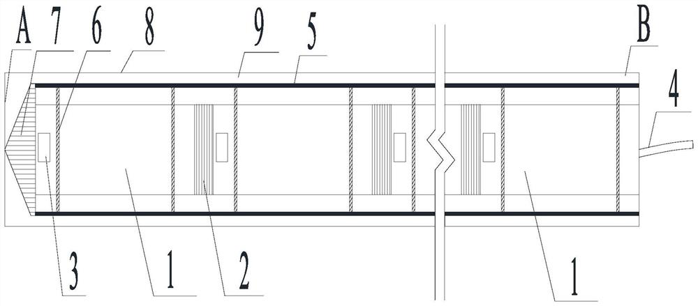
[0059] Such as figure 1 As shown, the present invention is a shield tunnel surrounding rock deformation advanced monitoring structure, including a monitoring body composed of several monitoring sections 1, flexible connecting sections 2 and angle sensing devices 3 located on the monitoring section 1, wherein the flexible connecting section 2 The two ends are respectively connected to the first section and the tail end of two adjacent monitoring sections 1, and the angle sensing device 2 is used to monitor the angle between the monitoring section 1 on it and the horizontal plane and the vertical plane.

Embodiment 2

[0061] On the basis of Embodiment 1, the flexible connecting section 2 respectively connects each adjacent monitoring section 1 with bolts in turn, and connects the cables of the angle sensing devices 3 in each adjacent monitoring section 1 during connection. In order to further fix the position of the monitoring body and protect it, the head end of the monitoring section 1 close to the A end is connected with a guide head 7 with a pointed cone at one end by bolts, and when the monitoring body is installed through the guide head 7 , play a guiding role.

[0062] Moreover, a flexible sleeve 5 is sleeved on the monitoring section 1 and the flexible connecting section 2, and the flexible sleeve 5 sleeves the monitoring main body therein. At this time, the guide head 7 is connected to the end of the flexible sleeve 5 near the A end, and the gap between the guide head 7 and the flexible sleeve 5 is sealed with a sealant, and waterproof treatment is performed to prevent the filler f...

Embodiment 3

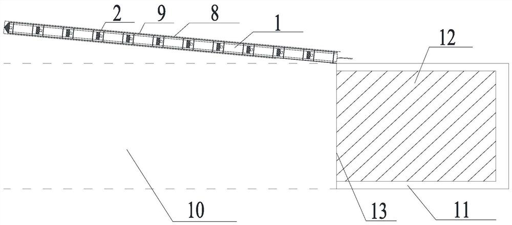
[0065] Such as figure 2 As shown, on the basis of embodiment 2, when in use, the monitoring main body is located in the advance borehole 8, and the advance borehole 8 is an obliquely upwardly inclined borehole above the unexcavated section 10 in the surrounding rock. The advance borehole 8 and The angle between the horizontal straight lines is 15°, the length of the advanced drilling 8 is 10m, and the length of a monitoring section 1 is 40cm.

[0066] In Embodiment 2, the monitoring body with the flexible sleeve 5 and the lead wire head 7 is placed in the advanced borehole 8, and after placement, a filler layer 9 for fixing the monitoring body is filled between the advanced borehole 8 and the monitoring body, The filler layer 9 of the device is cement mortar. After fixing, since the monitoring section 1 is a hollow steel pipe inside, the angle sensing device 2 is located inside the steel pipe. The angle sensing device 2 includes a first angle sensor and a second angle sensor...


PUM

PropertyMeasurementUnit
Lengthaaaaaaaaaa
Lengthaaaaaaaaaa
Lengthaaaaaaaaaa

Abstract

The invention discloses a shield tunnel surrounding rock deformation advanced monitoring structure and a monitoring method. The shield tunnel surrounding rock deformation advanced monitoring structurecomprises a monitoring main body composed of a plurality of monitoring sections, flexible connection sections and angle sensing devices arranged on the monitoring sections, and two ends of each flexible connection section are respectively connected with the head sections and the tail ends of two adjacent monitoring sections; the angle sensing devices are used for monitoring the angles between themonitoring sections on the angle sensing devices and the horizontal plane and the vertical plane. The device has the function of long-distance monitoring in the axis direction of the tunnel, deformation data of surrounding rocks with different pile numbers in the axis of the tunnel can be obtained through the multiple monitoring points of the monitoring body, and the monitoring result is more accurate.

Description

technical field [0001] The invention relates to the field of tunnels, in particular to an advanced monitoring structure and monitoring method for surrounding rock deformation of a shield tunnel. Background technique [0002] At present, most tunnel engineering monitoring technologies are created and used for drilling and blasting tunnels. However, due to the huge body of the shield machine itself, the excavation method of rock breaking with cutter heads, closed interior, limited operating space and no Having a contact channel with the surrounding rock limits the development of monitoring technology for tunnels constructed by the shield method, making it impossible to have a wide operating space like tunnels constructed by the drill and blast method, and various types of monitoring technologies can be used for monitoring. [0003] For shield tunnels, monitoring instruments such as earth pressure cells, multi-point displacement meters, and steel bar meters, which are widely us...

Claims


Application Information

Patent Timeline
IPC IPC(8): G01B21/32
CPCG01B21/32
Inventor 胡亚东张世殊冉从彦马金根
Owner POWERCHINA CHENGDU ENG
Why Eureka
Try Eureka