

Distributed type sensing device based on double-core double-wrapping layer optical fiber
A technology of double-clad optical fiber and sensing device, which is applied in the direction of multi-layer core/clad optical fiber, clad optical fiber, optical device, etc. Cost and other issues, to achieve the effect of good market prospects, long monitoring distance and low cost
- Summary
- Abstract
- Description
- Claims
- Application Information
AI Technical Summary
Problems solved by technology
Method used
Image

Examples
Embodiment 1
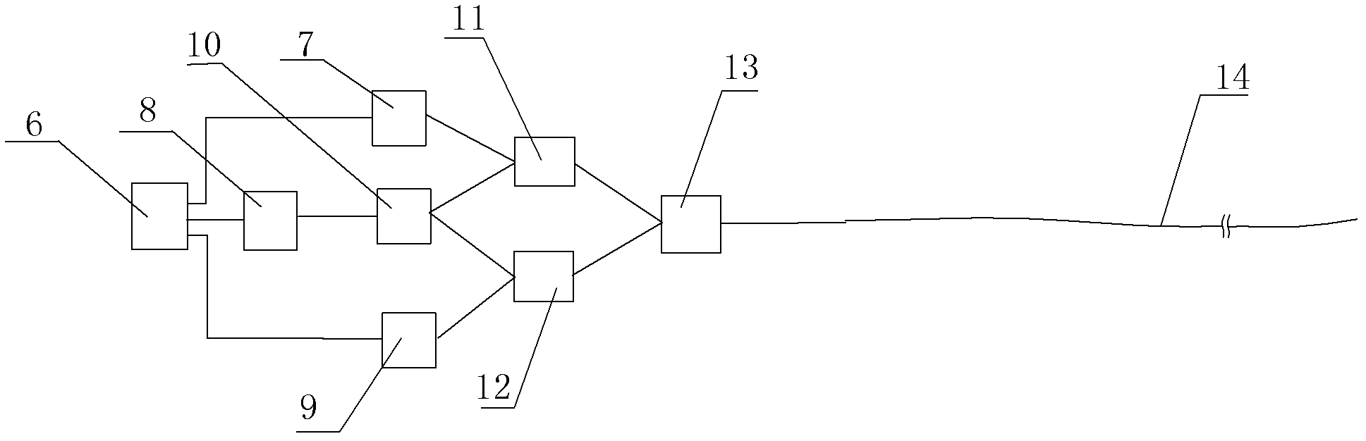
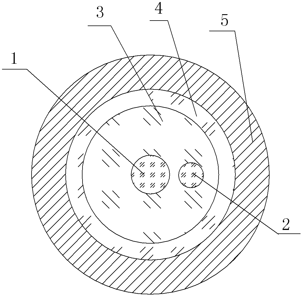
[0031] like figure 1 , figure 2 , image 3 A kind of distributed sensing device based on double-core double-clad optical fiber shown, comprises control module 6, light source module 8, photodetector module one 7 and photodetector module two 9, control module 6 and light source module 8, respectively The optical detector module one 7 is connected with the optical detector module two 9; the light source module 8 is connected with the 1 port of the 1×2 optical coupler 10, and the 2 ports of the 1×2 optical coupler 10 are connected with the 1 port respectively. One end of port 2 of ×2 optocoupler II 11 is connected to one end of port 2 of 1 × 2 optocoupler III 12, and the other end of port 2 of 1 × 2 optocoupler II 11 is connected to 1 × 2 optocoupler III The other end of port 2 of 12 is respectively connected with photodetector module 1 7 and photodetector module 2 9, port 1 of 1×2 photocoupler 2 11 and port 1 of 1×2 photocoupler 3 12 are respectively connected with The two n...
Embodiment 2
[0041] like Figure 4As shown, the difference between the present embodiment and the first embodiment is that the first photodetector module 7 and the second photodetector module 9 are connected to the differential amplifier 16 , and the differential amplifier 16 is connected to the control module 6 .
[0042] In this embodiment, the structures, connections and working principles of other parts are the same as those in Embodiment 1.
Embodiment 3
[0044] like Figure 5 As shown, the difference between this embodiment and Embodiment 1 is that an optical fiber delay line 15 is arranged between the first photodetector module 7 and the second 1×2 optical coupler 11 .
[0045] In this embodiment, the structures, connections and working principles of other parts are the same as those in Embodiment 1.
PUM
 Abstract
Description
Claims
Application Information