Vertical high-rise escape device and usage method thereof

An escape device and vertical technology, applied in life-saving equipment, building rescue and other directions, can solve the problems of not holding the escape rope tightly, high danger, time-consuming and labor-intensive escapers, etc., to achieve easy control of speed and high safety. , the effect of convenience

Pending Publication Date: 2018-12-18
GUIZHOU UNIV
View PDF2 Cites 0 Cited by
  • Summary
  • Abstract
  • Description
  • Claims
  • Application Information

AI Technical Summary

Problems solved by technology

[0002] When a fire breaks out in an existing high-rise building, the escape is usually through the fire platform. This method is time-consuming and laborious for the escapees, and the process of holding the escape rope for psychological reasons is prone to loose grip during the operation process, which is very dangerous.

Method used


Image

  • Vertical high-rise escape device and usage method thereof
  • Vertical high-rise escape device and usage method thereof
  • Vertical high-rise escape device and usage method thereof

Examples


Embodiment 1

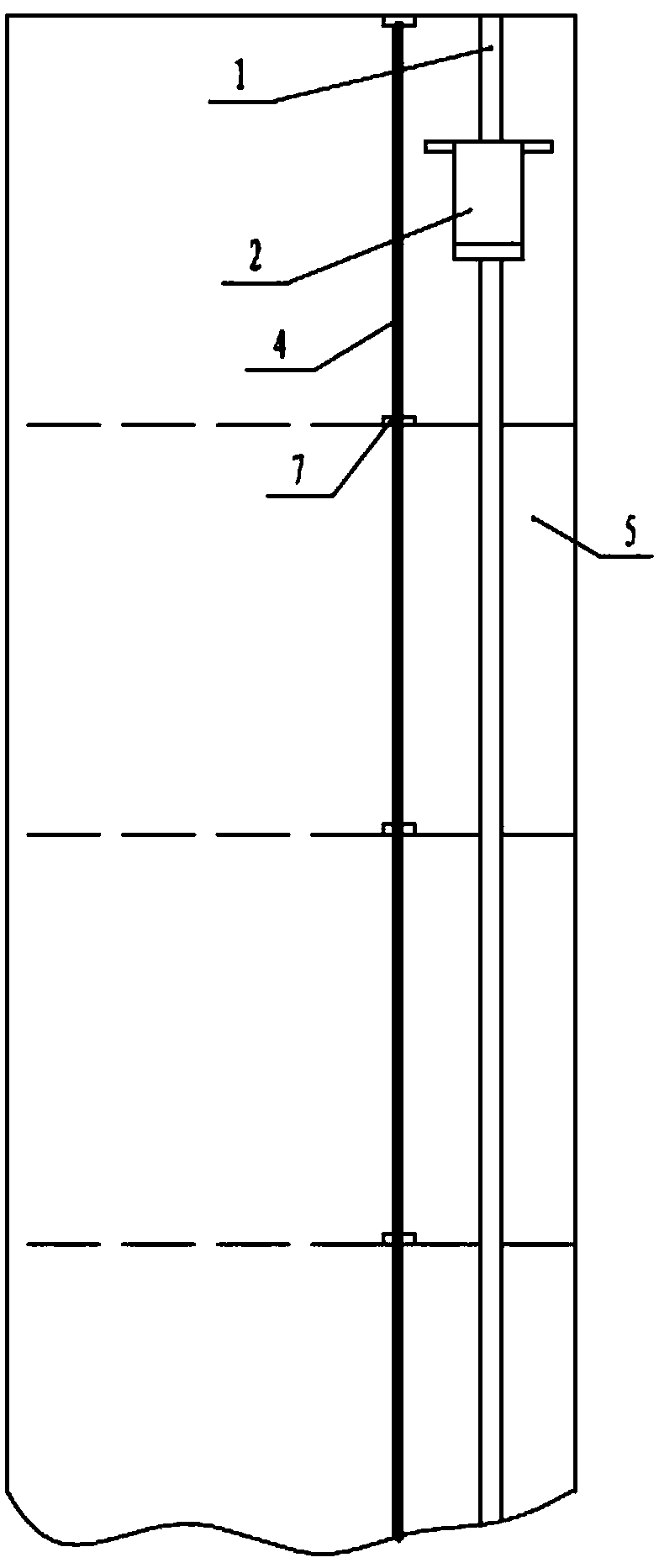
[0040] Embodiment 1: as Figure 1-Figure 4 As shown, a vertical high-rise escape device includes a vertical linear track 1 and a track trolley 2 installed outside the high-rise wall 5, the track trolley 2 is tightly connected to the linear track 1 through a friction slider 3 and the track trolley 2 When the load-bearing gravity is greater than the frictional force, it slides down, and it also includes a stay rope 4, which is installed next to the vertical linear track 1, and a limit sleeve 7 is set outside the wall 5 facing each floor to prevent the stay rope Suspended, unreliable to hold.

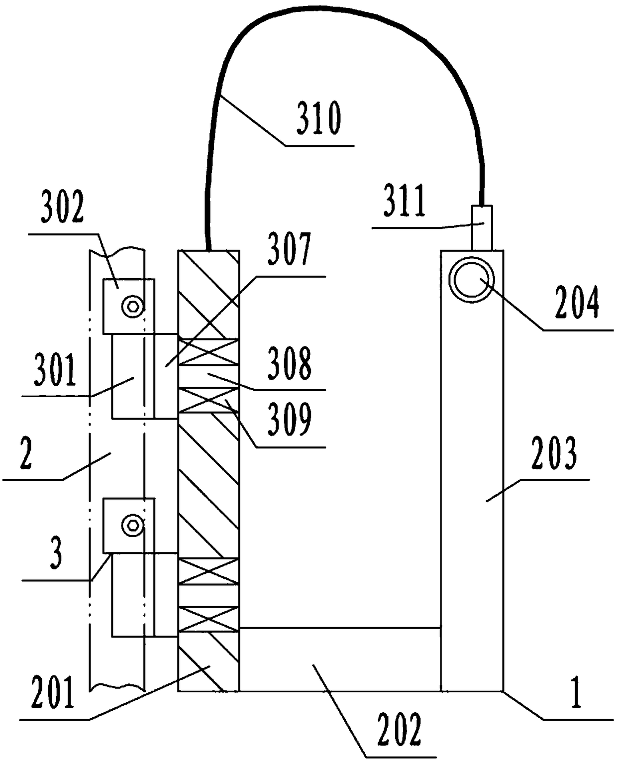
[0041] Preferably, the above-mentioned rail trolley 2 includes a slide plate 201, a cushion 202 and a backrest 203. Two friction sliders 3 are installed on the back side of the slide plate 201, and the bottom of the front side is vertically connected to the cushion 202. Skateboard 201 forms U-shaped structure, and linear track 1 is fixedly connected on the high-rise building wall 5 by I-s...

Embodiment 2

[0046] Embodiment 2: a method for using a vertical high-rise escape device, the method includes the following steps:

[0047] (1) Install the linear guide block and friction pair of the escape device on the linear track in sequence;

[0048] (2) Fasten the friction pair on the linear guide block and adjust the friction force;

[0049] (3) When in use, the human body sits on the cushion and faces the wall, with one hand leaning on the armrest, and the other hand pulling the drawstring;

[0050] (4) Give the escape device an initial force by external force or pulling the pull rope to obtain an initial speed;

[0051] (5) Under the action of friction, the human body descends to the ground along the straight track to realize escape.

[0052] The movement process of the escape device at the start and end of each floor satisfies:

[0053]

[0054] Among them, m is the total mass of the escape device and the person;

[0055] v 1 is the initial velocity;

[0056] h is the hal...


PUM


Abstract

The invention discloses a vertical high-rise escape device. The vertical high-rise escape device comprises a vertical linear track and a track trolley which are installed on the outer portion of a high-rise wall, wherein the track trolley is tightly connected to the linear track through a friction sliding block, and when the bearing gravity of the track trolley is greater than borne friction force, the track trolley slides downward. The vertical high-rise escape device further comprises a stay cord installed beside the vertical linear track. According to the vertical high-rise escape device, the escape device generates friction force on the linear track so as to descend at a uniform speed or in a deceleration mode, automatic falling is achieved without manual control, time and labor are saved, and besides, people do not need to worry, so that the mental tension issue is solved, In addition, by means of the stay cord, on the one hand, the braking function can be achieved and the speed can be controlled conveniently, and on the other hand, the operation safety is higher. The vertical high-rise escape device further has the characteristics of simple structure and low cost.

Description

technical field [0001] The invention relates to a vertical high-rise escape device and a use method thereof, belonging to the technical field of floor escape devices. Background technique [0002] When a fire breaks out in an existing high-rise building, escape is usually through the fire platform. This method is time-consuming and laborious for the escapees, and the process of grasping the escape rope due to psychological reasons is prone to loose grip during the operation, which is very dangerous. Contents of the invention [0003] The technical problem to be solved by the present invention is to provide a vertical high-rise escape device and its use method to solve the above-mentioned problems in the prior art. [0004] The technical solution adopted by the present invention is: a vertical high-rise escape device, including a vertical linear track and a track trolley installed outside the high-rise building wall, the track trolley is tightly connected to the linear trac...

Claims


Application Information

Patent Timeline
Patent Type & Authority Applications(China)
IPC IPC(8): A62B1/00
CPCA62B1/00
Inventor 崔韦达李泽滔
Owner GUIZHOU UNIV
Why Eureka
Try Eureka