Novel automatic thread slacking device of sewing machine

A technology of sewing machines and thread release devices, which is applied in the direction of sewing equipment, sewing machine components, sewing machine control devices, etc., can solve the problems of high requirements for parking workers, unfavorable parking workers, and troublesome operations, so as to save manpower and time, avoid Manual adjustment to avoid the effect of untimely operation

Pending Publication Date: 2018-12-18
陈梓豪
0 Cites 1 Cited by

AI-Extracted Technical Summary

Problems solved by technology

[0005] In the existing sewing machine, when the presser foot is lifted, the thread is loosened by means of the first thread clamp thimble 91 and the second thread clamp thimble 93, and the thread loosening nail matched inside the presser foot is jacked...

Method used

[0030] Preferably, the angle between one end of the side projection of the lever plate 7 and the horizontal e...

Abstract

The invention discloses a novel automatic thread slacking device of a sewing machine. The device comprises a thread clamping plate, a first thread clamping device, a tensioning coil, a second thread clamping device and a third thread clamping device are arranged on the thread clamping plate separately, a first thread clamping device thimble is arranged on the portion, of the back face of the of the thread clamping plate, of the first thread clamping device, and a second thread clamping device thimble is arranged on the portion, of the back face of the of the thread clamping plate, of the second thread clamping device. The novel automatic thread slacking device is characterized in that a lever plate is fixed to the back face of the thread clamping plate through a fixing hinge pin, the end,of the orthographic projection of the first thread clamping device thimble and the orthographic projection of the second thread clamping device thimble, of the lever plate is tilted, and a retractablemechanism for driving the lever plate is arranged at the other end of the lever plate. According to the novel automatic thread slacking device of the sewing machine, by using a lever principle, a pneumatic retractable rod is adopted for driving all the thread clamping device thimbles, the device is quick and efficient to use, manual adjustment is not needed, the labor and time are effectively saved, and the production efficiency is improved.

Application Domain

Sewing-machine control devicesTensioning devices

Technology Topic

Fixed hingeHinge angle +2

Image

  • Novel automatic thread slacking device of sewing machine
  • Novel automatic thread slacking device of sewing machine
  • Novel automatic thread slacking device of sewing machine

Examples

  • Experimental program(1)

Example Embodiment

[0025] In order to enable those skilled in the art to better understand the technical solutions of the present invention, the present invention will be described in detail below with reference to the accompanying drawings. The description in this section is only exemplary and explanatory and should not have any limitation on the scope of protection of the present invention. .
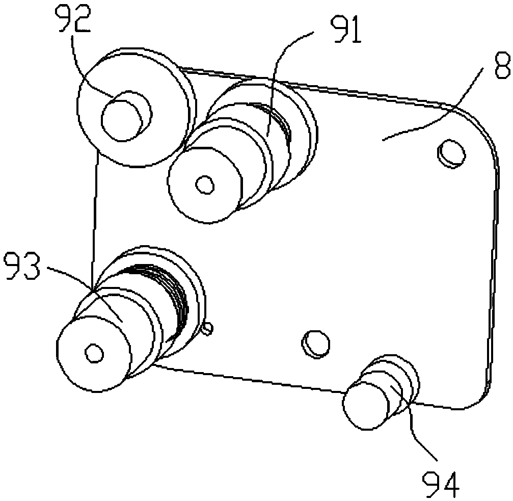
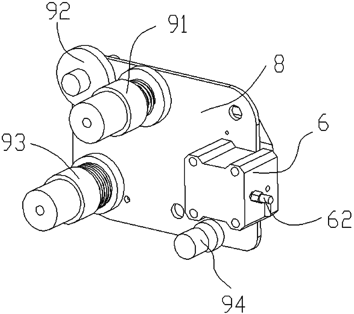
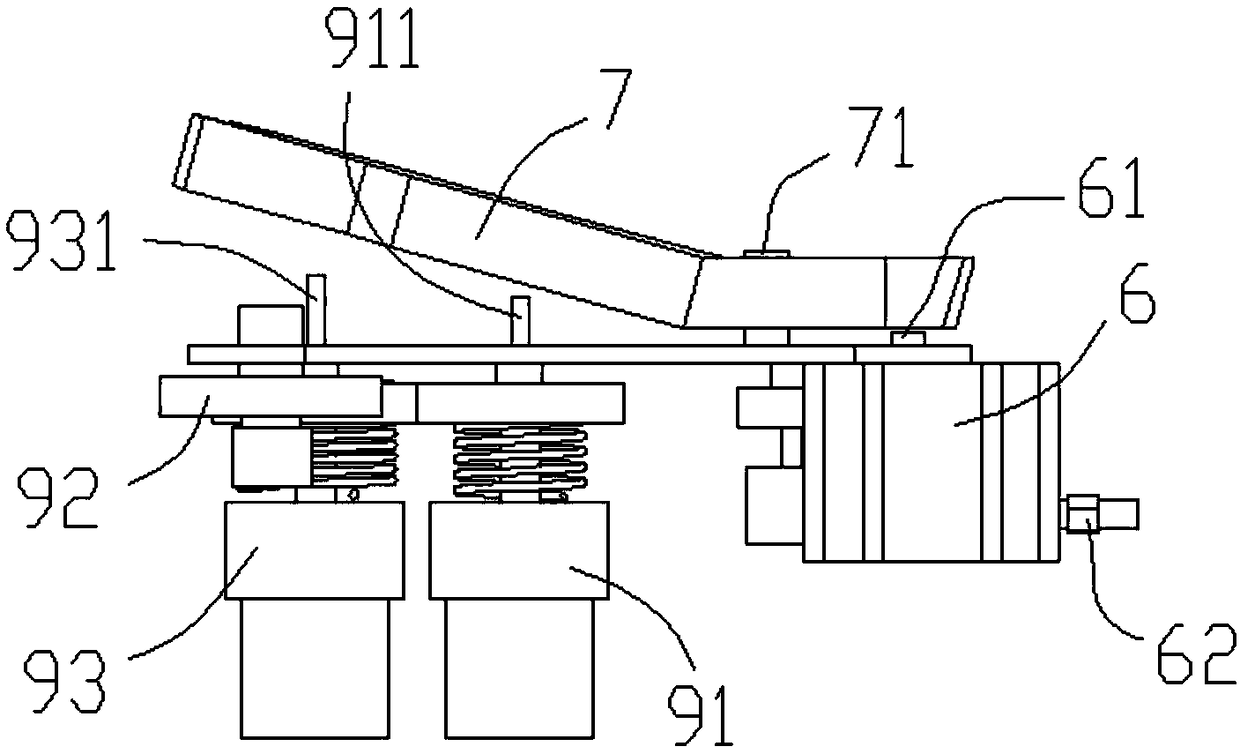
[0026] Such as Figure 2-Figure 5 As shown, the specific structure of the present invention is: a new type of automatic thread releaser for sewing machines, which includes a thread clamping plate 8 on which a first thread clamp 91, a tension coil 92, and a second thread clamp 93 are respectively arranged. The third thread clamp 93, and the first thread clamp 91 is provided with a first thread clamp thimble 91 on the back of the thread clamp plate 8, and the second thread clamp 93 is provided with a second thread clamp thimble on the back of the thread clamp plate 8. 93; characterized in that the back of the thread clamping plate 8 is fixed by the fixed pin 71 to the lever plate 7 and the lever plate 7 is at one end of the orthographic projection of the first thread clamp thimble 91 and the second thread clamp thimble 93. As a result, the other end of the lever plate 7 is provided with a telescopic mechanism for driving the lever plate 7.
[0027] Preferably, the telescopic mechanism is fixed on the front side of the wire clamping plate 8, and its retractable top rod 61 passes through the wire plate 8 and contacts the lever plate 7.
[0028] Preferably, the telescopic mechanism is a cylinder 6.
[0029] Preferably, the side-projected end of the lever plate 7 and the horizontal end form an angle structure.
[0030] Preferably, the angle between the tilted end of the side projection of the lever plate 7 and the horizontal end is 130°-170°. Such an angle design is convenient for pressing and releasing the thimble of the thread clamp.
[0031] Preferably, two fixing pins 71 are fixed on the wire clamping plate 8 and are arranged at an inclined angle.
[0032] Preferably, the horizontal fold line of the tilted end of the lever plate 7 is parallel to the horizontal line of the two fixing pins 71.
[0033] Participate in specific use Figure 2-Figure 5 When it is necessary to loosen the thread, the cylinder 6 takes in air from the inlet 62, and the cylinder 6 controls its ejector rod 61 to extend, and the ejector rod 61 hits the lever plate 7. Due to the fixed pin 71, the tilted lever plate 7 The thread clamp plate 8 moves, thereby compressing the thread clamp thimble (the first thread clamp thimble 91 and the second thread clamp thimble 93).
[0034] When the thread is loosened, the ejector rod 61 of the cylinder 6 retreats, the thread clamp thimble retreats under the action of the spring, the thread clamp tightens the thread, and the subsequent operation continues.
[0035] It should be noted that in this article, the terms "include", "include" or any other variants thereof are intended to cover non-exclusive inclusion, so that a process, method, article or device including a series of elements not only includes those elements, It also includes other elements not explicitly listed, or elements inherent to the process, method, article, or equipment.
[0036] Specific examples are used in this article to illustrate the principle and implementation of the present invention. The description of the above examples is only used to help understand the method and core idea of ​​the present invention. The above are only the preferred embodiments of the present invention. It should be pointed out that due to the limited expression of words, there are objectively infinite specific structures. For those of ordinary skill in the art, the principle of the present invention is not deviated from the premise Next, several improvements, modifications or changes can also be made, or the above technical features can be combined in an appropriate manner; these improvements, changes or combinations, or the concept and technical solution of the invention can be directly applied to other occasions without improvement , Should be regarded as the protection scope of the present invention.

PUM

no PUM

Description & Claims & Application Information

We can also present the details of the Description, Claims and Application information to help users get a comprehensive understanding of the technical details of the patent, such as background art, summary of invention, brief description of drawings, description of embodiments, and other original content. On the other hand, users can also determine the specific scope of protection of the technology through the list of claims; as well as understand the changes in the life cycle of the technology with the presentation of the patent timeline. Login to view more.

Similar technology patents

Chemical reagent storing device

Owner:TIANJIN XINYUAN GUANGTAI NEW MATERIAL TECH CO LTD

Steam boiler for automatically adding fuel

InactiveCN111750343ASave manpower and timePrevent flying air from polluting the air
Owner:杭州慧晟科技有限公司

Full-automatic wire forming equipment

Owner:广东领航精密机械设备科技有限公司

Indoor mini-type crushed soil sieving machine

InactiveCN104772183AConvenient soil crushing and sieving operationSave manpower and time
Owner:CHINA THREE GORGES UNIV +2

Classification and recommendation of technical efficacy words

  • Increase productivity
  • Save manpower and time

Preparation method of super-retarding type polycarboxylate superplasticizer

ActiveCN103848944AIncrease productivityUniform product
Owner:KZJ NEW MATERIALS GROUP CO LTD
Why Eureka
Try Eureka