

Building concrete solid pile
A technology of concrete and solid piles, applied in construction, sheet pile walls, foundation structure engineering, etc., can solve problems such as insufficient bearing strength and poor tension stability, achieve high strength and stability, good seismic performance, and comprehensive improvement The effect of mechanical properties
Active Publication Date: 2018-12-18
ZHEJIANG OCEAN UNIV
View PDF6 Cites 0 Cited by
- Summary
- Abstract
- Description
- Claims
- Application Information
AI Technical Summary
Problems solved by technology
[0007] However, the above-mentioned solid piles still have the problems of insufficient bearing strength and poor tension stability.
Method used
View moreImage
Smart ImageViewing Examples

Examples
Embodiment Construction
[0035] In order to make the technical solution of the present invention clearer, the present invention will be further described below in conjunction with the accompanying drawings. Any solution obtained by equivalent replacement and conventional reasoning of the technical features of the technical solution of the present invention falls within the protection scope of the present invention.
Login to View More PUM
 Abstract
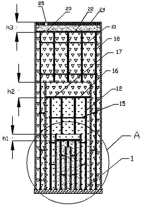
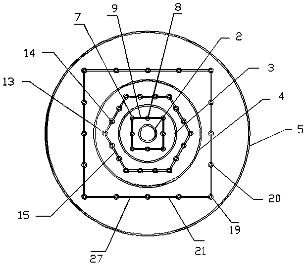
The invention provides a building concrete solid pile in order to solve the problems. The building concrete solid pile comprises a base; a first supporting ring, a second supporting ring, a third supporting ring and a fourth supporting ring are disposed on the base in sequence from inside to outside; the inner diameters as well as the heights of the first supporting ring, the second supporting ring, the third supporting ring and the fourth supporting ring are gradually increased; a first steel reinforcement cage of which the end surface is of a square structure is disposed between the first supporting ring and the second supporting ring; a second steel reinforcement cage of which the end surface is of a regular hexagon structure is disposed between the second supporting ring and the thirdsupporting ring; and a third steel reinforcement cage of which the end surface is of a square structure is disposed between the third supporting ring and the fourth supporting ring. By means of the building concrete solid pile, the comprehensive mechanical property of the whole foundation pile is improved, the strength and stability are improved, and the anti-seismic property is good.
Description
technical field [0001] The invention relates to a solid pile, in particular to a concrete solid pile for construction. Background technique [0002] There are many building materials for foundation pile engineering in the market, such as pipe piles, various square piles, cast-in-situ piles, bored piles, etc. These piles are mainly divided into two categories: non-prestressed components and prestressed components. Prestressed component piles include pipe piles, centrifugal prestressed square piles, etc. Their disadvantages are that they are often brittle, the time from cracking to failure is short, and the ductility of the pile body is poor. When an earthquake occurs, the building collapses instantly, so that the people in the building do not have enough time to escape. [0003] Existing concrete prefabricated components have various cross-sections, most of which are square and circular cross-sections on the market. When used as load-bearing components, the biggest purpose ...
Claims
Login to View More Application Information
Patent Timeline
 IPC IPC(8): E02D5/30
CPCE02D5/30
Inventor艾万政
OwnerZHEJIANG OCEAN UNIV