
Suspended structure with multiple combination modes

A hanging piece and hanging hole technology, applied in building components, building structures, buildings, etc., can solve the problems of high decoration cost, complex construction process, low construction efficiency, etc., and achieve convenient construction and low technical level requirements. , install fast effect

Inactive Publication Date: 2018-12-18
北京秦长城新型建材有限公司
View PDF2 Cites 0 Cited by
  • Summary
  • Abstract
  • Description
  • Claims
  • Application Information

AI Technical Summary

Problems solved by technology

In the process of keel installation, the construction process is complicated, the construction efficiency is low, it consumes a lot of manpower, and the decoration cost is high. At the same time, the technical level of the decoration personnel is also high. The traditional decoration technology can no longer meet the needs of the current industrialization of architectural decoration.

Method used


Image

  • Suspended structure with multiple combination modes
  • Suspended structure with multiple combination modes
  • Suspended structure with multiple combination modes

Examples


no. 2 example

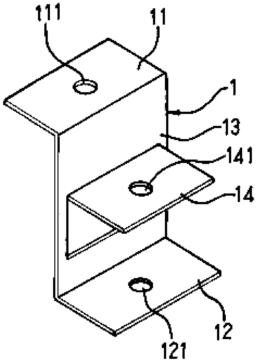
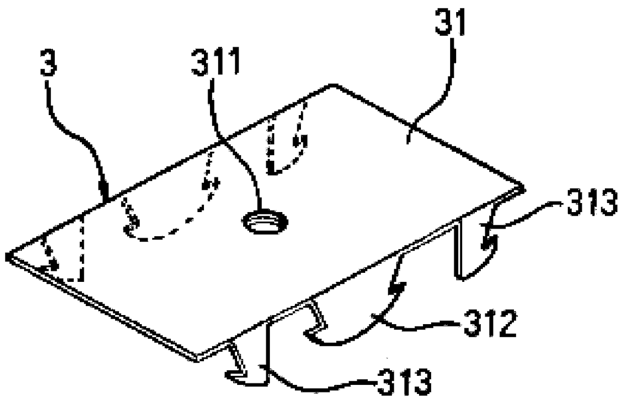
[0051] Such as Figure 7 As shown, first use a nail gun to fix the steel nail 6 to the roof surface through the fixing hole 111 of the upper plate 11 of the roof surface hanging part 1, and then insert the screw rod 7 into the first hanging hole 121 and the second hanging hole 121. Hole 141, the upper end of the screw rod 7 is fixed with a nut, the lower end of the screw rod 7 is connected with the sheet body screw hole 311 on the sheet body 31 of the cladding keel hanger 3, and then the first hook on the two sides of the cladding keel B B1 and the second hook B2 are hooked on the two pairs of hooks 313 on the cladding joist hanger 3, so that the cladding joist B is hooked in the up and down direction, and the cladding joist B can be on the two pairs of buckles 313 Slide horizontally to facilitate the installation and construction of the cladding keel B.

[0052] Such as Figure 8 As shown, similarly, a pair of buckle teeth 312 on the cladding keel hanger 3 can be hooked wit...

no. 3 example

[0054] Such as Figure 10 As shown, first use a nail gun to fix the steel nail 6 to the roof surface through the fixing hole 111 of the upper plate 11 of the roof surface hanging part 1, and then penetrate the screw rod 7 into the fourth hole on the T-shaped keel hanging part 5 in sequence. Hanging hole 531, the third hanging hole 511 and the first hanging hole 121 and the second hanging hole 141 on the roof surface hanging piece 1, the upper end of the screw rod 7 is fixed with a nut, and the lower end of the screw rod 7 is also fixed with a nut , and then hang the end of the T-shaped keel C riser in the hanging interface 521 of the T-shaped keel hanging part 5, so that the T-shaped keel C is suspended in the up and down direction, and the T-shaped keel C can be hung on the hanging interface. 521 slide horizontally. The lower part of the connecting plate 52 is provided with an opening 5211 for allowing the riser of the T-shaped keel C to pass through, so that the end of the ...


PUM


Abstract

The invention discloses a suspended structure with multiple combination modes. The suspended structure comprises a roof surface suspended piece, a loading keel suspended piece, a covered surface keelsuspended piece, a loading keel and covered surface keel buckling piece and a T-shaped keel suspended piece which are connected with the roof surface suspended piece; the roof surface suspended piececan be fixed to a roof surface, so that the loading keel suspended piece, the covered surface keel suspended piece, the loading keel and covered surface keel buckling piece, the T-shaped keel suspended piece and other components are combined with a loading keel, a covered surface keel, a T-shaped keel and the like on the suspended piece of the roof surface in a buckled or suspended mode, thereby providing convenience for the construction operation of various suspended ceilings. The suspended structure with multiple combination modes has the advantages that the installation is fast, the construction is convenient, the cost is saved, and the technical requirements of construction personnel are low.

Description

technical field [0001] The invention relates to the technical field of construction, in particular to a hanging structure with multiple combinations. Background technique [0002] The hanging construction of traditional building decoration generally uses an electric drill to drill holes, then drives expansion bolts into the holes and fixes them with nuts. In the process of keel installation, the construction process is complicated, the construction efficiency is low, it consumes a lot of manpower, and the decoration cost is high. At the same time, the technical level of the decoration personnel is also high. The traditional decoration technology can no longer meet the needs of the current industrialization of architectural decoration. Contents of the invention [0003] Aiming at the deficiencies in the prior art, the purpose of the present invention is to provide a hanging structure with multiple combinations that is fast in installation, convenient in construction, cost-s...

Claims


Application Information

Patent Timeline
Patent Type & Authority Applications(China)
IPC IPC(8): E04B9/18
CPCE04B9/18E04B9/183
Inventor 蔡金河
Owner 北京秦长城新型建材有限公司
Learn More