A magnetic resistance linkage damping device for electromechanical equipment

A technology of electromechanical equipment and shock absorption device, which is applied to mechanical equipment, supporting machines, machines/brackets, etc., can solve the problems of reducing vibration of mechanical equipment, single shock absorption mode, and large limitations, and is conducive to popularization and application, reducing Good shock effect, good shock absorption effect

Active Publication Date: 2020-05-08
青岛静科环保技术有限公司
View PDF5 Cites 2 Cited by
  • Summary
  • Abstract
  • Description
  • Claims
  • Application Information

AI Technical Summary

Problems solved by technology

[0003] The shock absorption of existing mechanical equipment or the protective measures for contact with the ground are too simple and the effect is not good. For machines that generate strong vibration during work, simple shock absorbers will not play any substantial role. The shock absorber is installed under the base of the machine tool or other mechanical equipment, which can adjust the level of the mechanical equipment and greatly reduce the vibration of the mechanical equipment. Using the shock absorber to replace the original rigid fixed support of the anchor bolts saves labor and time and does not need to be damaged. The ground can also improve the installation accuracy of the equipment. The commonly used shock absorbing devices are mainly springs and rubber pads.
[0004] However, the existing shock absorbers have poor shock absorption and support effects on electromechanical equipment, single shock absorption mode, unreasonable structural design, and large limitations.

Method used


Image

  • A magnetic resistance linkage damping device for electromechanical equipment
  • A magnetic resistance linkage damping device for electromechanical equipment
  • A magnetic resistance linkage damping device for electromechanical equipment

Examples


Embodiment Construction

[0022] The following will clearly and completely describe the technical solutions in the embodiments of the present invention with reference to the accompanying drawings in the embodiments of the present invention. Obviously, the described embodiments are only some, not all, embodiments of the present invention. Based on the embodiments of the present invention, all other embodiments obtained by persons of ordinary skill in the art without making creative efforts belong to the protection scope of the present invention.

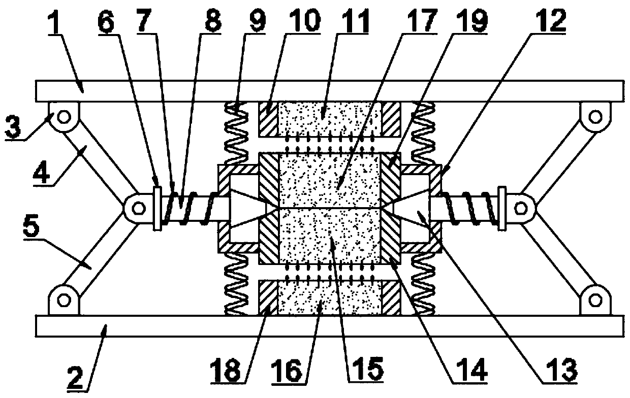
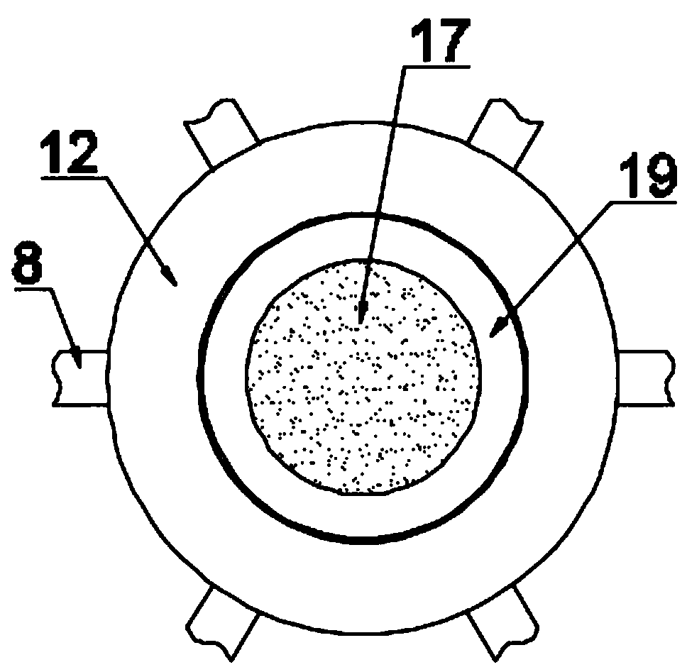
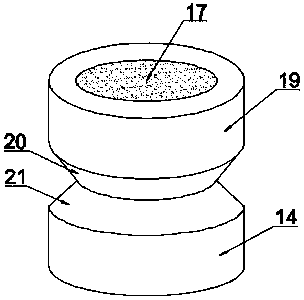
[0023] see Figure 1~3 , in an embodiment of the present invention, a reluctance linkage damping device for electromechanical equipment includes a bearing plate 1, a bottom plate 2, an upper strut 4, a lower strut 5, and a mounting plate 12, and the gap between the load plate 1 and the base plate 2 is A mounting plate 12 is provided, and the mounting plate 12 is a hollow disc-shaped structure. A first sleeve 19 and a second sleeve 14 are installed in the middl...


PUM


Abstract

The invention discloses a magnetic-resistance linkage damping device of electromechanical equipment. The magnetic-resistance linkage damping device of the electromechanical equipment comprises a carrying plate, a base plate and a mounting disc. The mounting disc is arranged between the carrying plate and the base plate. A first sleeve and a second sleeve are mounted at the top and the bottom of the mounting disc. A third magnet and a fourth magnet are separately mounted in the first sleeve and the second sleeve. A first fixing sleeve is mounted above the first sleeve and is located on the lower side of the carrying plate. A first magnet is mounted in the first fixing sleeve. A second fixing sleeve is mounted below the second sleeve and is located on the upper side of the base plate. A second magnet is mounted in the second fixing sleeve. A plurality of cross rods are mounted on the outer side of the mounting disc in the circumferential direction. Stamping blocks are mounted at the inner ends of the cross rods and are located on the inner side of the mounting disc. Baffles are mounted at the outer ends of the cross rods. Upper supporting rods and lower supporting rods are hinged tothe outer sides of the baffles through hinge supports. The magnetic-resistance linkage damping device of the electromechanical equipment is good in damping effect, novel in structure, reasonable in design, capable of stably supporting the electromechanical equipment and easy to apply and popularize.

Description

technical field [0001] The invention relates to the field of electromechanical technology, in particular to a reluctance linkage damping device for electromechanical equipment. Background technique [0002] With the rapid development of China's manufacturing industry, the electromechanical equipment required by the manufacturing industry is also developing towards large-scale and heavy weight. In most cases, large-scale electromechanical equipment is placed directly on the ground, and its bottom is generally in direct contact with the ground. Or simply add shims under the foot stand, the purpose of which is to prevent the machine tool from crushing the ground and fracturing it. [0003] The shock absorption of existing mechanical equipment or the protective measures for contact with the ground are too simple and the effect is not good. For machines that generate strong vibration during work, simple shock absorbers will not play any substantial role. The shock absorber is in...

Claims


Application Information

Patent Timeline
Patent Type & Authority Patents(China)
IPC IPC(8): F16F15/03F16F15/04F16M11/04
CPCF16F15/03F16F15/04F16M11/046
Inventor 束鑫
Owner 青岛静科环保技术有限公司
Why Eureka
Try Eureka