Flow limiting valve and filling equipment

A technology of restricting valve and valve body, applied in valve device, mechanical equipment, lift valve, etc., can solve the problem of no adjustment effect, and achieve the effect of sensitive adjustment, easy cleaning and simple operation

Pending Publication Date: 2018-12-18
GUANGZHOU TECH LONG PACKAGING MACHINERY CO LTD
View PDF0 Cites 1 Cited by
  • Summary
  • Abstract
  • Description
  • Claims
  • Application Information

AI Technical Summary

Problems solved by technology

[0002] In general filling conditions, the flow limiting effect can be achieved by adding a flow limiting plate to the front-end pipeline of the filling, but the flow limiting plate achieves the adjustment effect through the size of the orifice hole, and has no adjustment effect

Method used


Image

  • Flow limiting valve and filling equipment
  • Flow limiting valve and filling equipment
  • Flow limiting valve and filling equipment

Examples


Embodiment Construction

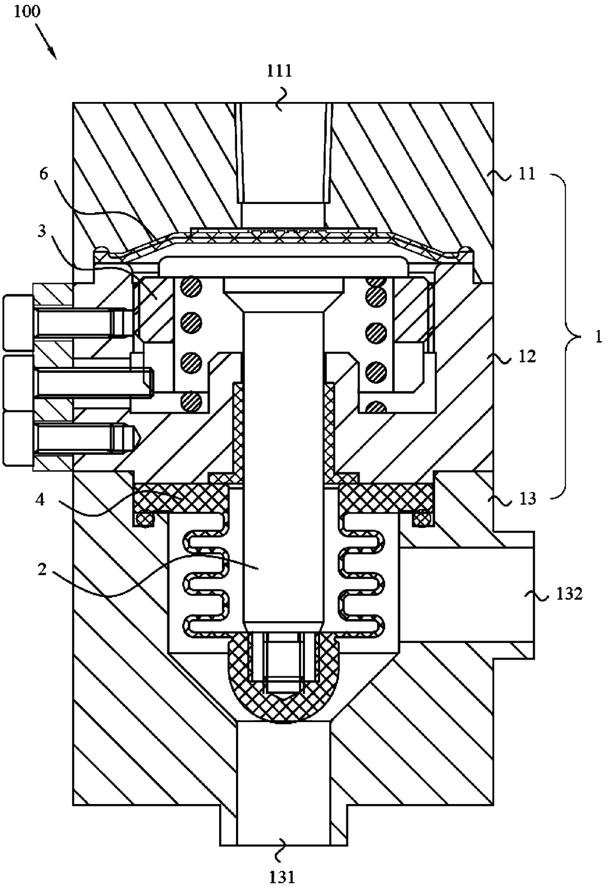
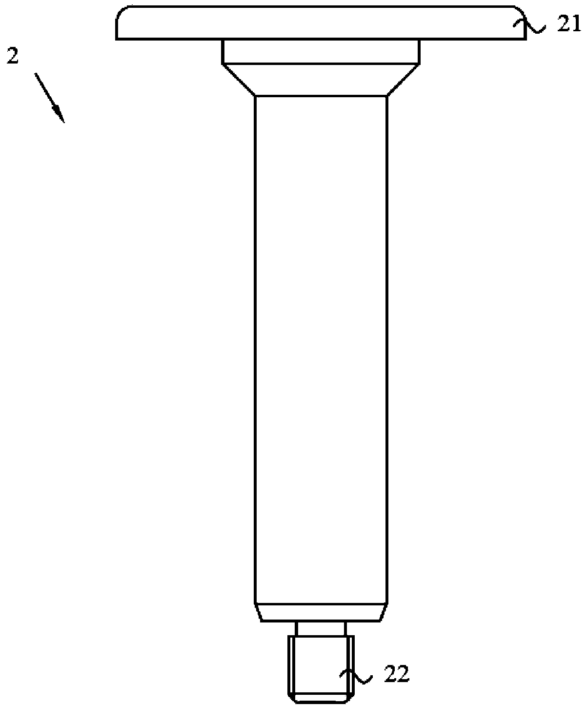
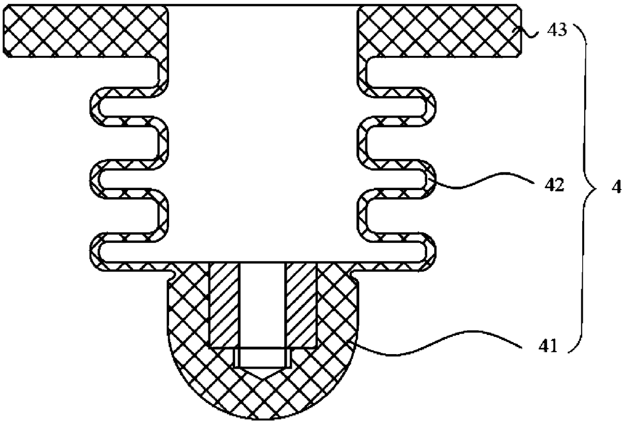
[0040] In order to enable those skilled in the art to better understand the technical solution of this embodiment, the technical solution of this embodiment will be further described below in conjunction with the accompanying drawings and through specific implementation methods.

[0041] In the description of the present invention, it should be noted that the terms "upper", "lower", "left", "right", "vertical", "horizontal", "inner", "outer", "inlet" , "Liquid Out" and other indications are based on the orientation or positional relationship shown in the attached drawings, or the orientation or positional relationship that is usually placed when the product is used, and are only for the convenience of describing the present invention, not to indicate Or imply that the device or element referred to must have a specific orientation, be constructed and operate in a specific orientation, and therefore should not be construed as limiting the invention.

[0042] like figure 1 to co...


PUM


Abstract

The invention relates to the technical field of filling equipment, in particular to a flow limiting valve and filling equipment. The flow limiting valve comprises a valve body, a valve core and a limiting component, wherein the valve body is provided with a liquid inlet passage, a liquid outlet passage, a power source passage and an accommodating cavity, and the liquid inlet passage, the liquid outlet passage, the power source passage and the accommodating cavity communicate with each other. The valve core and the limiting component are disposed in the accommodating cavity. One end of the valve core is arranged opposite to the power source passage. The position of the valve core can be limited by the limiting component, so that the gap of the valve core relative to the liquid outlet passage can be adjusted. According to the flow limiting valve, because the limiting component is high in repeated positioning precision, and flexible to adjust, different flow limiting effects can be achieved, and the operation is easy. By adopting the flow limiting valve, the filling equipment can be conveniently cleaned without any dead angle of hygiene.

Description

technical field [0001] The invention relates to the technical field of filling equipment, in particular to a flow limiting valve and filling equipment. Background technique [0002] In general filling conditions, the flow limiting effect can be achieved by adding a flow limiting plate to the front-end pipeline of the filling, but the flow limiting plate achieves the adjustment effect through the size of the orifice hole, and has no adjustment effect. In actual application, it is necessary to match different liquid flow rates for different usage occasions. For example, when doing pipeline positioning cleaning, it is usually desirable to have a larger liquid flow rate to improve the cleaning effect, while in other occasions a smaller liquid flow rate is required. . [0003] Therefore, there is an urgent need to design a flow limiting structure to achieve the purpose of adjustable flow, so as to meet different needs in different situations. Contents of the invention [0004...

Claims


Application Information

Patent Timeline
Patent Type & Authority Applications(China)
IPC IPC(8): F16K1/32F16K1/36
CPCF16K1/32F16K1/36
Inventor 罗志成张聪敏宋俊杰黄龙强
Owner GUANGZHOU TECH LONG PACKAGING MACHINERY CO LTD
Why Eureka
Try Eureka