
A 3D Point Cloud Motion Compensation Method

A technology of motion compensation and three-dimensional point cloud, which is applied in the direction of instruments, measuring devices, and utilization of re-radiation, etc., can solve the problems of missing scans in target areas, affecting reconstruction accuracy, performance defects, etc., achieve high compensation accuracy and improve motion compensation accuracy , The effect of improving the accuracy

Active Publication Date: 2020-11-10
BEIJING INST OF CONTROL ENG
View PDF5 Cites 0 Cited by
  • Summary
  • Abstract
  • Description
  • Claims
  • Application Information

AI Technical Summary

Problems solved by technology

[0003] Wang Jianjun et al. 2011 in the "Influence of Attitude Angle Perturbation on Airborne LiDAR Point Cloud Data" in the Journal of Instrumentation, due to the interference of various internal and external factors during the actual flight process, such as gusts, turbulence, engine vibration and control system Performance defects, etc., the airborne platform cannot maintain the ideal uniform linear motion state, resulting in attitude angle disturbances, resulting in changes in the scanning area and density distribution of the point cloud
Changes in the point cloud scanning area, for the measurement of narrow and long areas, such as roads, coastlines and power lines, will lead to missed scanning of the target area; changes in point cloud density will affect the accuracy of reconstruction

Method used


Image

  • A 3D Point Cloud Motion Compensation Method

Examples


Embodiment

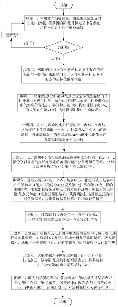
[0044] A kind of three-dimensional point cloud motion compensation method, each step is described in detail below:

[0045] Step 1. Use the laser to scan the target, the camera receives the reflected light from the laser, scans the first group of target point clouds obtained, and stores the three-dimensional coordinate values ​​of each point in the camera coordinate system;

[0046] If it is found that the scanned point cloud is the first group, continue to step 1 to scan the second group of point clouds and store the three-dimensional coordinates; then find that the number of point cloud scans i is 2, greater than 1, go to step 2;

[0047] Step 2. Calculate the average value (10,10,100) of the coordinate values ​​of all points of the second group of point clouds in the camera coordinate system; calculate the average value of the coordinate values ​​of all points of the first group of point clouds in the camera coordinate system ( 16,16,106);

[0048] Step 3. Match the second...


PUM


Abstract

The invention relates to a three-dimensional point cloud motion compensation method, comprising the following steps: respectively connecting central points, scanned twice, of a point cloud with central points, scanned twice, of a target shape; respectively selecting one point from two connections, and traversing until two points with the nearest distance are gotten; calculating a mean value of thetwo nearest points, and taking the mean value point as a suspected target rotation center coordinate; taking the suspected target rotation center coordinate as an original point, traversing positionsin a plurality of ranges, and performing motion compensation by taking the traversed positions as a point cloud rotation center respectively; calculating a rotation center, movement speed of a targetcentral position and target rotational angular velocity, taking the numerical values as a basis, calculating a relative position error of each point, compensating each point in the point cloud, and then calculating a matching error of a compensated scanned point cloud with a target profile point cloud; traversing other rotation centers and performing motion compensation on the scanned point cloud, and getting the matching errors of the compensated point cloud; and taking one group of compensated scanned point clouds with the smallest matching error, and taking as a final compensated point cloud. The three-dimensional point cloud motion compensation method provided by the invention is high in point cloud compensation accuracy.

Description

technical field [0001] The invention relates to a three-dimensional point cloud motion compensation method. Background technique [0002] Laser point cloud has been widely used in target position and attitude calculation. When the laser scans the non-cooperative target, due to the time interval between point cloud collection, if the relative movement speed or rotational angular velocity of the non-cooperative target and the laser is too fast, the position of the scanned point cloud and the actual shape point of the target will be offset. If the point cloud in this case is used for position and attitude calculation, errors will occur. Therefore, in the case of too fast movement of the target or too fast rotation of its own attitude, it is necessary to perform point cloud motion compensation processing on the scanned point cloud to eliminate the position error of the point cloud and the corresponding calculated position and attitude error. [0003] Wang Jianjun et al. 2011 i...

Claims


Application Information

Patent Timeline
Patent Type & Authority Patents(China)
IPC IPC(8): G01S17/42
CPCG01S17/42
Inventor 王立刘达张春明李涛吴云朱飞虎顾营迎刘忠汉
Owner BEIJING INST OF CONTROL ENG
Learn More