
Motion compensation method suitable for FPSO upper module lifting and installing process

An installation process and motion compensation technology, applied in the field of motion compensation, can solve the problems of damage to the upper module of the FPSO, the adjustment of the upper module pose, and the inability to complete the docking accurately, and achieve the effect of simple control strategy, high installation accuracy and strong timeliness

Pending Publication Date: 2022-01-18
BOMESC OFFSHORE ENG CO LTD
View PDF0 Cites 0 Cited by
  • Summary
  • Abstract
  • Description
  • Claims
  • Application Information

AI Technical Summary

Problems solved by technology

The lifting and installation process of the FPSO upper module lasts for a long time, and the attitude of the FPSO hull will change due to the impact of environmental loads such as wind, waves, currents, and tides on the pier, resulting in the inability to accurately complete the docking during the loading process, which may seriously damage the FPSO upper module , causing massive economic losses
At present, the lifting and installation process of the upper module of the FPSO is mainly to select a suitable operation window period and reduce the influence of environmental factors, and the motion compensation system is not used to adjust the pose of the upper module
The current FPSO topside module lifting and installation system cannot fully meet the actual engineering needs, and an efficient, reliable, simple and easy motion compensation method is urgently needed during the FPSO topside module lifting and installation process

Method used


Image

  • Motion compensation method suitable for FPSO upper module lifting and installing process
  • Motion compensation method suitable for FPSO upper module lifting and installing process
  • Motion compensation method suitable for FPSO upper module lifting and installing process

Examples


Embodiment Construction

[0047] Below in conjunction with accompanying drawing, the present invention is described in detail:

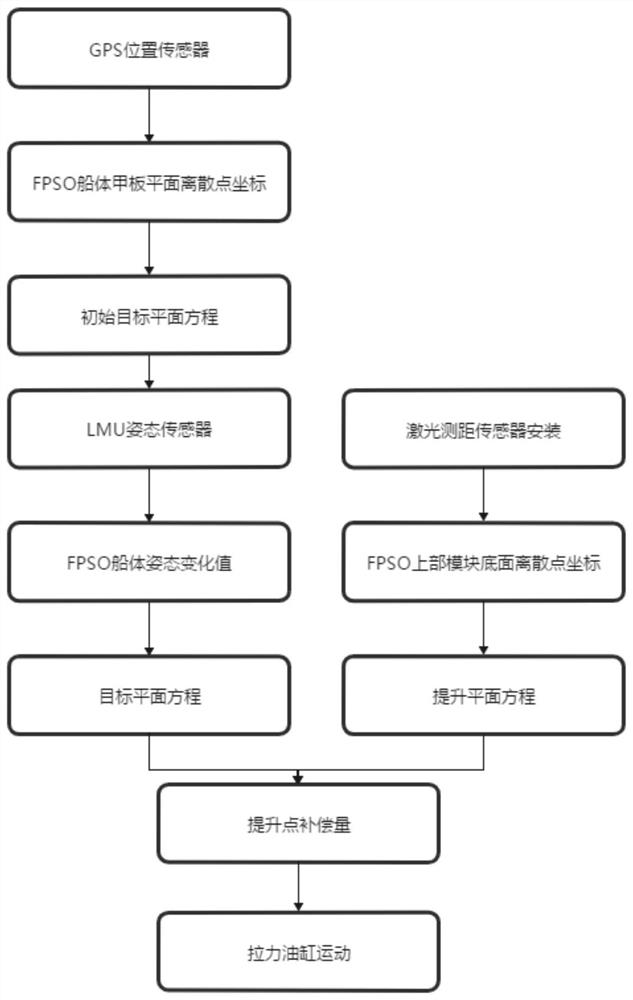
[0048] As shown in the accompanying drawings, the motion compensation method applicable to the lifting and installation process of the FPSO upper module of the present invention includes the following steps:

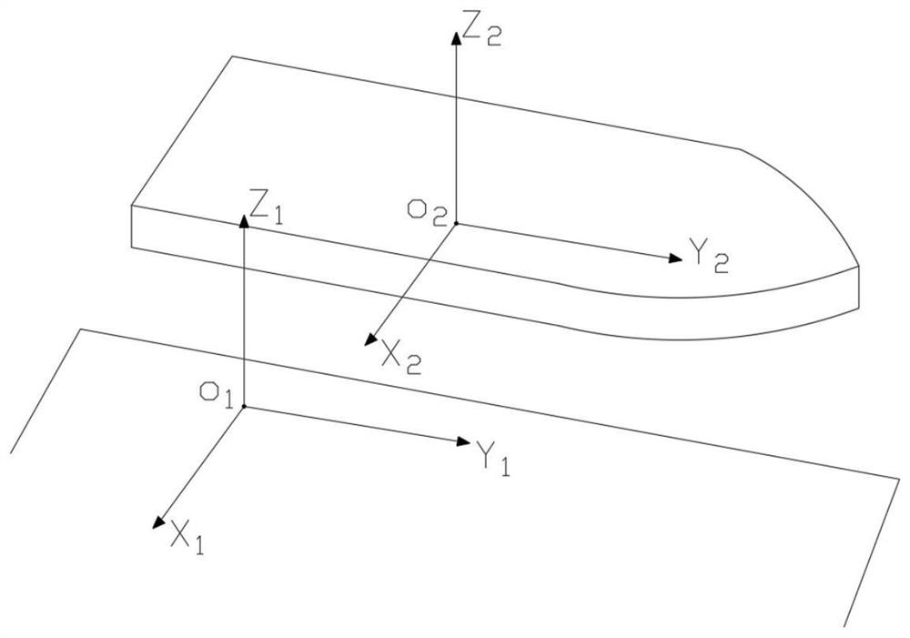
[0049] Step 1. Establish the global coordinate system and the hull coordinate system. The specific process is as follows:

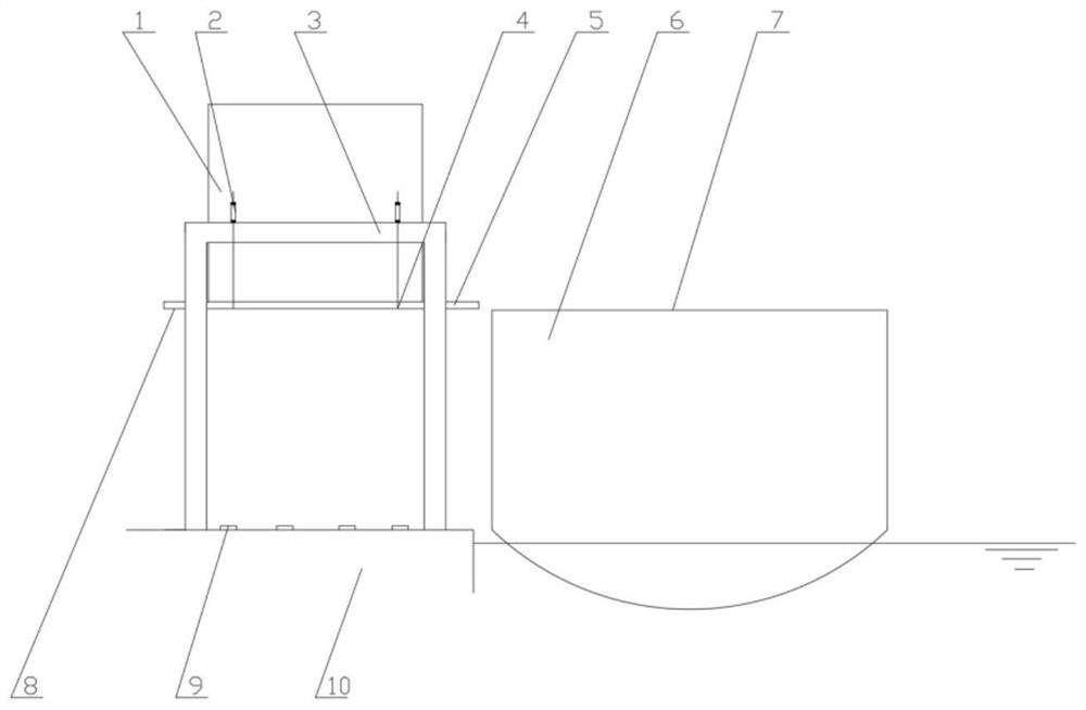
[0050] In the first step, the hoisting system of the upper module of the FPSO is a hoisting installation support structure 3 composed of multiple towers. There are four oil cylinders 2, and the elevating rods of the four tension cylinders 2 form a rectangle, and the elevating rods of the tension cylinders 2 arranged in the vertical direction are fixedly connected with the upper ends of the steel strands, and the bottom ends of the steel strands are welded on the lifting On the bottom plate 5, the position of the welding point is the position 4 of ...


PUM


Abstract

The invention discloses a motion compensation method suitable for the lifting and installing process of an FPSO upper module. The method comprises the steps of establishing a global coordinate system and a ship body coordinate system; calculating an initial target plane equation in the FPSO upper module installation process by using a GPS position sensor; calculating an FPSO upper module installation process target plane equation by using an RMU pose sensor; calculating a lifting plane equation of the FPSO upper module installation process through a laser distance measuring sensor; calculating the compensation amount of each lifting point in the installation process of the FPSO upper module; synchronously increading lifting heights of all the tension oil cylinders in a lifting installation system which is set in the computer, and gradually lifting the FPSO upper module to the position coplanar with the FPSO ship deck plane. According to the method, the butt joint precision is greatly guaranteed, the safety of the installation process is guaranteed, the change of the marine environment on a wharf can be efficiently dealt with, and the problems that in the FPSO upper module lifting installation process, the FPSO ship body pose change is fast, and the butt joint precision is poor can be effectively solved.

Description

technical field [0001] The invention relates to a motion compensation method, in particular to a motion compensation method suitable for the lifting and installation process of an FPSO upper module. Background technique [0002] The installation of the FPSO upper module is generally divided into two types: lifting installation and suspension installation. The lifting installation uses hydraulic cylinders to lift the FPSO upper module to the height of the FPSO deck and then slides the ship. This method has a strong bearing capacity and high stability, and is gradually being used. widely used. The lifting and installation process of the FPSO upper module lasts for a long time, and the attitude of the FPSO hull will change due to the impact of environmental loads such as wind, waves, currents, and tides on the pier, resulting in the inability to accurately complete the docking during the loading process, which may seriously damage the FPSO upper module , causing massive econom...

Claims


Application Information

Patent Timeline
Patent Type & Authority Applications(China)
IPC IPC(8): B63B75/00B66C13/46B66C13/18
CPCB63B75/00B66C13/46B66C13/18
Inventor 王京风盖晓琳
Owner BOMESC OFFSHORE ENG CO LTD
Learn More