[0021] The present invention will be further described below in conjunction with the accompanying drawings.
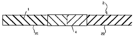
[0022] like figure 1 and figure 2 , a construction optical cable for color bar identification for opening skylights according to the present invention, comprising an optical fiber, a loose tube 1 and an outer sheath 3. The sleeve 3 is wrapped on the cable core 2 . The cable core 2 includes a forward twisted part 21 and a reverse twisted part 22. Both the forward twisted part 21 and the reverse twisted part 22 of the cable core are wrapped with a fixing belt, and the fixing belt ensures the twisted The cable core 2 is not loose, and the fixing belt includes a gauze tape and a transparent polyester tape wrapped on the cable core in turn from the inside to the outside.
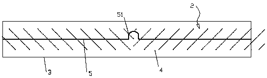
[0023] A marker block 4 is attached at the position (junction) of the forward twisted part 21 and the reverse twisted part 22 of the cable core, and a colored ribbon 5 is arranged on the side wall of the outer sheath 3 along the Arranged in the axial direction of the outer sheath 3 , a twist point 51 is provided on the ribbon, and the position of the twist point 51 corresponds to the position of the identification block 4 .
[0024] Optical cable construction and splicing operators can quickly identify the position of the cable core SZ twisting and reversing point through the characteristics of the external torsion point 51 of the optical cable, so as to carry out targeted stripping construction work, which greatly reduces the work of "opening the skylight" construction of optical cables Quantity and improve construction efficiency, saving labor cost of optical cable construction.
[0025] The material of the sheath material 3 in the present invention is polyethylene, and the material of the color ribbon 5 is polyethylene whose color is different from that of the sheath material, and the color ribbon 5 and the outer sheath 3 are integrally formed by extrusion.
[0026] The production method of the color bar identification skylight construction optical cable of the present invention comprises the following steps:
[0027] 1) Manufacturing steps of loose tube 1.
[0028] 2) The step of threading the optical fiber into the loose tube 1.
[0029] 3) A step of forward-twisting and reverse-twisting several loose tubes 1 with optical fibers through the SZ twisting device to form a cable core 2 .
[0030] 4) The step of longitudinally wrapping the fixing tape on the forward and reverse stranding surface in the cable core 2 and fixing the cable core.
[0031] 5) Attach the identification block 4 at the position of the forward and reverse twisted reversing points in the cable core 2, pass the cable core 2 into the mold cavity of the extruder used to extrude the outer sheath, and One side of the extruder is provided with a probe for photographing the marking block;
[0032] 6) The extruder extrudes the outer sheath 3 to form a ribbon arranged along the axial direction of the outer sheath 3 on the outer wall of the outer sheath 3, and the outer sheath is wrapped on the cable core to finally form an optical cable; The material of casing material 3 is polyethylene, and the material of ribbon 5 is polyethylene whose color is different from that of the sheath material. The pouring method and corresponding mold structure for forming ribbon 5 on the outer wall of outer sheath 3 are all prior art, so this The invention no longer repeats in detail how the colored ribbon 5 and the outer sheath 3 are integrally formed by extrusion.
[0033] 7) The formed optical cable is pulled from the extruder to the water cooling tank through the twisting tractor 6. When the probe hits the marking block, the probe transmits a signal to the twisting tractor, and makes the twisting tractor twist and return .
[0034] 8) The twisting and returning of the twisting tractor 6 makes the outer sheath 3 twist and return together during the extrusion process, and then the ribbon 5 on the outer wall of the outer sheath 3 produces a twist point 51, and the position of the twist point 51 is obtained Corresponds to the position of identification block 4.
[0035] The above steps 1), 2), 3) and 4) are all conventional steps in the production process of optical cables, and the production process involved in each step is the same as that in the prior art, so the present invention does not make any further adjustments to steps 1)-4). Go into details.
[0036] The detection point of the marker block 4 is in the pay-off section, and there is still a distance to reach the head of the extruder, so the twisting tractor 6 needs to calculate the delay time according to the length of this distance, and then match the current production speed. In this way, it is ensured that the curved ribbon formed by twisting coincides with the position of the color block detected internally. The time difference is controlled by computer software, which is a conventional means in the prior art, so the present invention will not repeat them in detail.
[0037] like image 3 , the twisting tractor 6 among the present invention comprises mounting seat 61, upper driving belt 62, lower driving belt 63, upper tensioning wheel group 64, lower supporting wheel group 65, connecting shaft 66, driven gear 67, driving gear 68 , stepper motor, mounting frame and drive motor, mounting seat 61 is connected on the mounting frame 69 in rotation, upper driving belt 62 and lower driving belt 63 are arranged in the mounting seat 61 up and down, and the lower side in the upper driving belt 62 A feeding gap 60 is formed between the driving side belt and the upper driving side belt in the lower driving belt 63, and the upper tension wheel set 64 and the lower supporting wheel set 65 are respectively arranged on the inner side of the upper driving belt 62 and the lower driving belt 63. The inner side, and the upper tension wheel set 64 elastically interferes with the lower driving side belt in the upper driving belt 62 . The upper driving side belt in the lower driving belt 63 is supported on the lower support wheel set 65, and the driving motor drives the upper driving belt 62 to rotate. The connecting shaft 66 is fixedly connected with the mounting base 61, the driven gear 67 is fixed on the connecting shaft 66, the driving gear 68 is fixedly connected with the output shaft of the stepping motor, and the driving gear 68 is meshed with the driven gear 67, and the stepping motor is fixed. On the mounting frame 69 , the stepping motor rotates forward or reverse according to the signal transmitted by the probe, and the forward rotation and reverse rotation of the stepping motor correspond to the rotation and return of the mounting base 61 .
[0038] Support rollers are set on the mounting frame 69, and arc roller grooves are set on the outer wall of the mounting seat 61, and the arc roller grooves are supported on the support rollers.
[0039]The upper tension wheel set 64 elastically resists the lower driving side belt in the upper driving belt 62 through an elastic mechanism. This elastic mechanism comprises guide rod 71, spring 72, pressing plate 73 and adjusting screw 74, and pressing plate 73 is placed in mounting base 61, and two guide rods 71 pass mounting base 61 and pressing plate 73 successively, and the bottom end of guiding rod 71 and upper The wheel seat of the tensioning wheel set 64 is fixedly connected, the spring 72 is sleeved on the guide rod 71, and the bottom end of the spring 72 is in contact with the wheel seat, and the top of the spring 72 is in contact with the pressing plate 73 on the guide rod 71, and the adjustment The screw 74 is screwed on the mounting base 61 , and the bottom end of the adjusting screw 74 is in contact with the pressing plate 73 . Rotate the adjusting screw 74 to adjust the tension of the upper tension wheel set 64 .
[0040] A stepped surface is provided on the guide rod 71 , and the spring 72 pushes the pressure plate 73 against the stepped surface of the guide rod 71 .
[0041] A feeding hole is provided in the axial direction of the connecting shaft 66, and the feeding hole communicates with the feeding gap 60. When in use, the optical cable passes through the feeding hole and extends in the feeding gap 60.
[0042] Use the probe to detect the position of the identification block 4 at the SZ twisting point where the cable core is twisted, and the probe transmits a signal to the twisting tractor 6 to drive the outer sheath to twist (that is, torsion and twist back action). The operation can make the color ribbon 5 extruded on the surface of the outer sheath of the optical cable twist and return at the position of the SZ twisting and reversing point. From the visual effect, it can be seen that the originally straight color ribbon 5 is at the SZ twisting and reversing point. The torsion and torsion return pattern (that is, the torsion point 51) occurs, thereby achieving the effect of locating the position of the SZ twisting reversing point.
[0043] The above is only a preferred embodiment of the present invention, it should be pointed out that for those of ordinary skill in the art, some improvements can also be made without departing from the principle of the present invention, and these improvements should also be regarded as the invention. protected range.