Outdoor drop cable

A technology for introducing optical cables and optical cables, applied in the directions of light guides, optics, optical components, etc., can solve the problems of not fully meeting the laying requirements and inconvenient construction, and achieve the effect of shortening the laying period and use cost, convenient construction, and reducing connection points.

Pending Publication Date: 2018-12-18
JIANGSU HENGTONG PHOTOELECTRIC
View PDF0 Cites 2 Cited by
  • Summary
  • Abstract
  • Description
  • Claims
  • Application Information

AI Technical Summary

Problems solved by technology

The laying methods of the three major home-entry optical cable structures described above can no longer fully meet the laying requirements. The combination of two kinds of optical cables, that is, the combination of the cable type that meets the requirements for outdoor laying and the cable type that meets the requirements for indoor laying, needs to increase the connection point in the process of introducing the outdoor into the indoor, which will undoubtedly bring a lot of inconvenience to the construction

Method used


Image

  • Outdoor drop cable

Examples


Embodiment

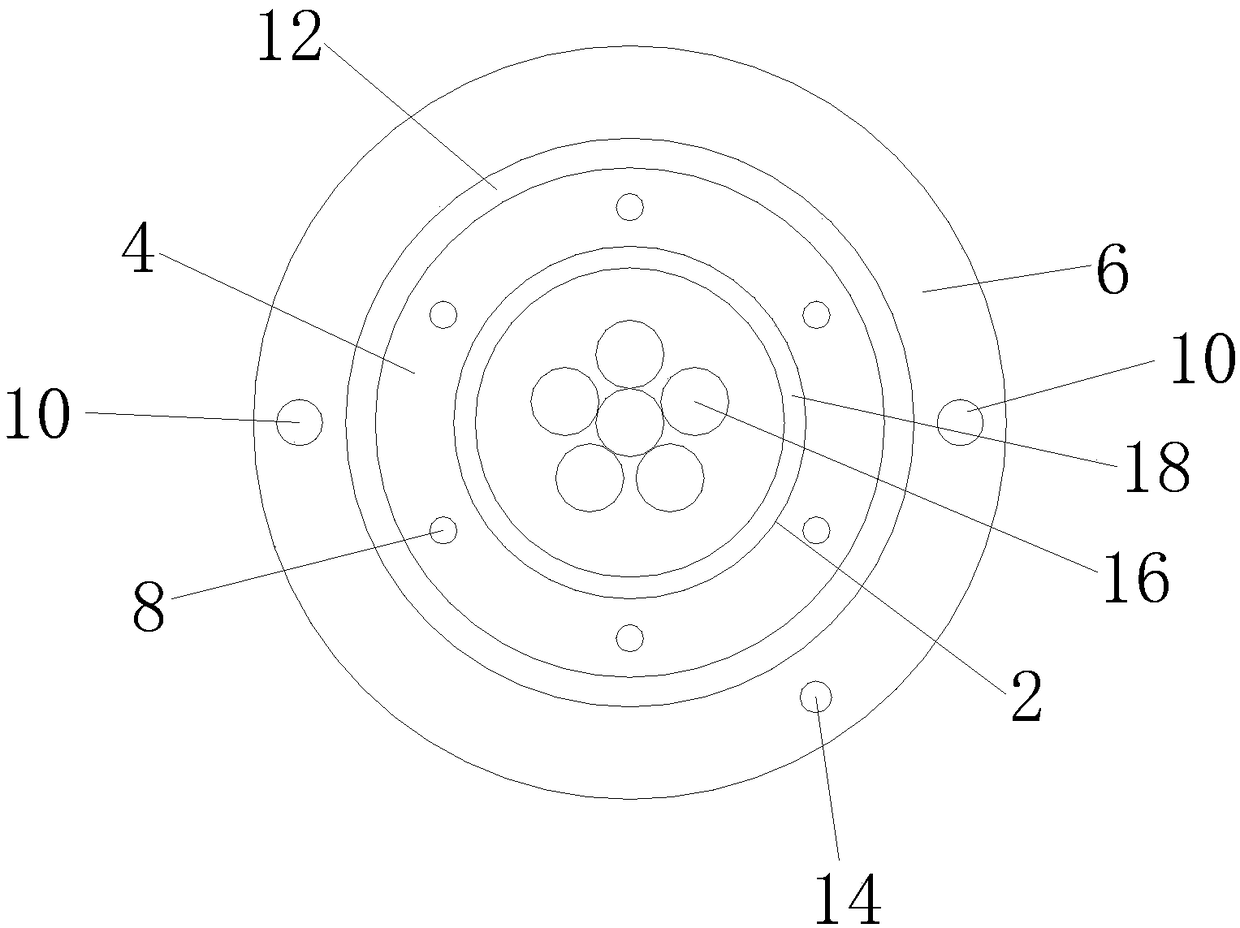
[0020] refer to figure 1 As shown, the present invention discloses an outdoor lead-in optical cable. The cross-section of the above-mentioned optical cable is circular, and it includes a cable core 2, an inner sheath layer 4 coated on the outside of the above-mentioned cable core 2, and an inner sheath layer coated on the outer side of the cable core 2. 4 the outer non-metallic protective layer 12, and the outer sheath layer 6 covering the outer side of the non-metallic protective layer 12. The cable core 2 includes an optical fiber unit 16 and an insulating layer 18 covering the optical fiber unit 16 , and fiber paste or dry flexible water-blocking yarn is filled between the optical fiber unit 16 and the insulating layer 18 .

[0021] Such as figure 1 As shown, the above-mentioned inner sheath layer 4 is embedded with six first non-metallic reinforcing cores 8, and the above-mentioned six first non-metallic reinforcing cores 8 are distributed on concentric circles with the c...


PUM


Abstract

The invention discloses an outdoor drop cable. The cross section of the cable is circular. The outdoor drop cable comprises a cable core, an inner sheath layer covering the outer side of the cable core, and an outer sheath layer covering the outer side of the inner sheath layer, wherein six first non-metallic strengthening cores are embedded into the inner sheath layer, and distributed on a concentric circle with the center of the cable core as the circle center in an equal-central-angle manner; and the six first non-metallic strengthening cores are all embedded synchronously in the process offorming the inner sheath layer. The optimized cable structure of the outdoor drop cable enables the cable to meet various laying requirements such as overhead, direct burying, pipelines and outdoor into indoor, and construction becomes convenient. After use of the outdoor drop cable, the construction period and cost of cable laying can be reduced greatly, and the connecting points of outdoor to indoor layering are reduced.

Description

technical field [0001] The invention belongs to the technical field of optical cable communication, and in particular relates to a conveniently laid outdoor lead-in optical cable. Background technique [0002] Traditional optical cables are divided into three types: aerial, direct buried and pipeline according to the laying method. Outdoor aerial optical cables are generally 8-shaped self-supporting optical cables with hanging wires and circular self-supporting optical cables; outdoor direct-buried optical cables are generally metal armored. Round optical cables are mainly used; outdoor duct optical cables are generally metal armored or non-metallic optical cables; indoor optical cables are generally tight-buried optical cables, which require softness and flame retardancy. The optical cables of these structures are the optical cable structures widely used in China at present. [0003] With the development of FTTH construction in recent years, the laying environment of FTTH ...

Claims


Application Information

Patent Timeline
Patent Type & Authority Applications(China)
IPC IPC(8): G02B6/44
CPCG02B6/443G02B6/4432G02B6/44384
Inventor 张鑫元史惠萍顾利国李惠强顾小峰詹学龙孙伟盛惠良崔仲敏张萍
Owner JIANGSU HENGTONG PHOTOELECTRIC
Why Eureka
Try Eureka