Concrete layer pouring construction method and highway

A technology of plate-like components and concrete layers, which is applied in the directions of roads, buildings, roads, etc., can solve the problems such as the unsmooth turning radian of the road body, the shortened radian of the curved form, and the unsatisfactory construction period, so as to avoid the concrete layer from being damaged. The effect of reducing damage, smooth road turning arc, and shortening the road laying period

Active Publication Date: 2022-04-08
衡阳市金铭环境科技有限公司
View PDF12 Cites 0 Cited by
  • Summary
  • Abstract
  • Description
  • Claims
  • Application Information

AI Technical Summary

Problems solved by technology

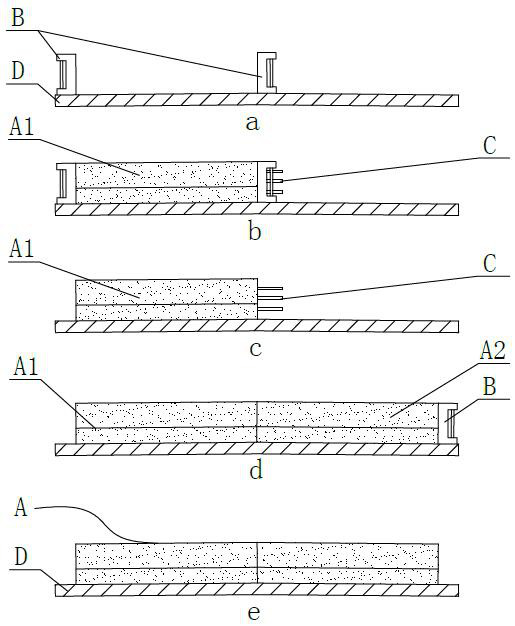
Before pouring concrete, steel form B needs to be installed first, and steel form B needs to be dismantled after the concrete has solidified and reached the design strength. Due to the strong bonding force between the solidified concrete and steel form B interface, the steel form B on the inner side (i.e. The steel form on the side of the other half that has not been poured) still has lapped steel bar C passing through the reinforcement hole. In many cases, it is necessary to use a steel drill to pry the steel form B, and the steel drill to pry off the steel form B It is easy to damage the concrete surface during the process, resulting in defects on the concrete surface, and the road shoulder filling construction must be carried out after the steel form B is removed, and the construction period is difficult to shorten
In addition, the existing steel form B is mostly made of straight steel. In some sharp curve sections, the paved road body does not turn smoothly, and the aesthetics are not high.
[0003] At present, most of the improvement methods for the above problems focus on changing the connection and fixing structure of steel form B to make the assembly operation of steel form B easier (that is, how to quickly install the formwork), but how to make it easier to remove the formwork, how to make the There is still no satisfactory solution for the smoother arc of the corner molding and how to shorten the construction period

Method used


Image

  • Concrete layer pouring construction method and highway
  • Concrete layer pouring construction method and highway
  • Concrete layer pouring construction method and highway

Examples


Embodiment Construction

[0032] It should be noted in advance that in the present invention, unless otherwise specified and limited, the terms "installation", "connection", "connection", "fixation" and other terms should be understood in a broad sense, for example, it can be a fixed connection, It can also be detachably connected or integrally connected; it can be directly connected or indirectly connected through an intermediary. Those of ordinary skill in the art can understand the specific meanings of the above terms in the present invention according to specific situations.

[0033] Furthermore, in the present invention, the terms "upper", "lower", "front", "rear", "left", "right", "top", "bottom", "inner", "outer" and the like indicate The orientation or positional relationship is based on the orientation or positional relationship shown in the drawings, and is only for the convenience of describing the present invention and simplifying the description, rather than indicating or implying that the ...


PUM


Abstract

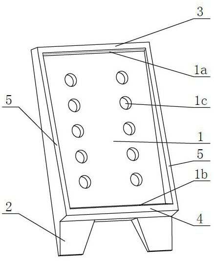
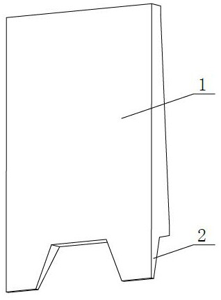
A piled plate-shaped member, a construction method for concrete layer pouring of a road, and a road relate to the technical field of highway engineering. The aforementioned piled plate-shaped member includes a plate-shaped member body as a whole, and a pile head is arranged below the member body. The pile head is connected with the component body above as a whole, and a pile tip is formed at the bottom of the pile head, and the component body is provided with a gripping part that is convenient for people to grasp to lift the pile plate-shaped member and is convenient for people to lift. A stepping portion for stepping on the foot to insert the pile head downward. The sheet-like member with piles can replace the existing steel formwork and be used as a formwork for pouring concrete layers. Using the sheet-like member with piles is easy to install and easy to operate, flexible in construction, can save formwork removal time, shorten the road laying period, and can also Form a smoother road turning arc, which is beneficial to improve the aesthetics of the road.

Description

technical field [0001] The invention relates to the technical field of highway engineering, in particular to a construction method for pouring a concrete layer of a highway with a pile-plate-like component and a highway. Background technique [0002] See figure 1 As shown, when laying the concrete layer A of the road, most of the existing methods divide the road surface into two halves with the center line of the road surface as the boundary, lay one half first, and lay the other half after the concrete has solidified to a certain strength. Before pouring concrete, steel form B needs to be installed first, and steel form B needs to be dismantled after the concrete has solidified and reached the design strength. Due to the strong bonding force between the solidified concrete and steel form B interface, the steel form B on the inner side (i.e. The steel form on the side of the other half that has not been poured) still has lapped steel bar C passing through the reinforcement ...

Claims


Application Information

Patent Timeline
Patent Type & Authority Patents(China)
IPC IPC(8): E01C5/08E01C19/50
CPCE01C5/08E01C19/502
Inventor 谢金钊谢飞帆陶林辉
Owner 衡阳市金铭环境科技有限公司
Why Eureka
Try Eureka