

Camera lens group
A camera lens and camera lens technology, applied in the field of camera lens sets, can solve the problems of low infrared transmittance, difficult to improve optical distortion, and inability to meet imaging requirements in the near-infrared band, and achieve high imaging quality and high light transmission. rate effect
- Summary
- Abstract
- Description
- Claims
- Application Information
AI Technical Summary
Problems solved by technology
Method used
Image

Examples
Embodiment 1
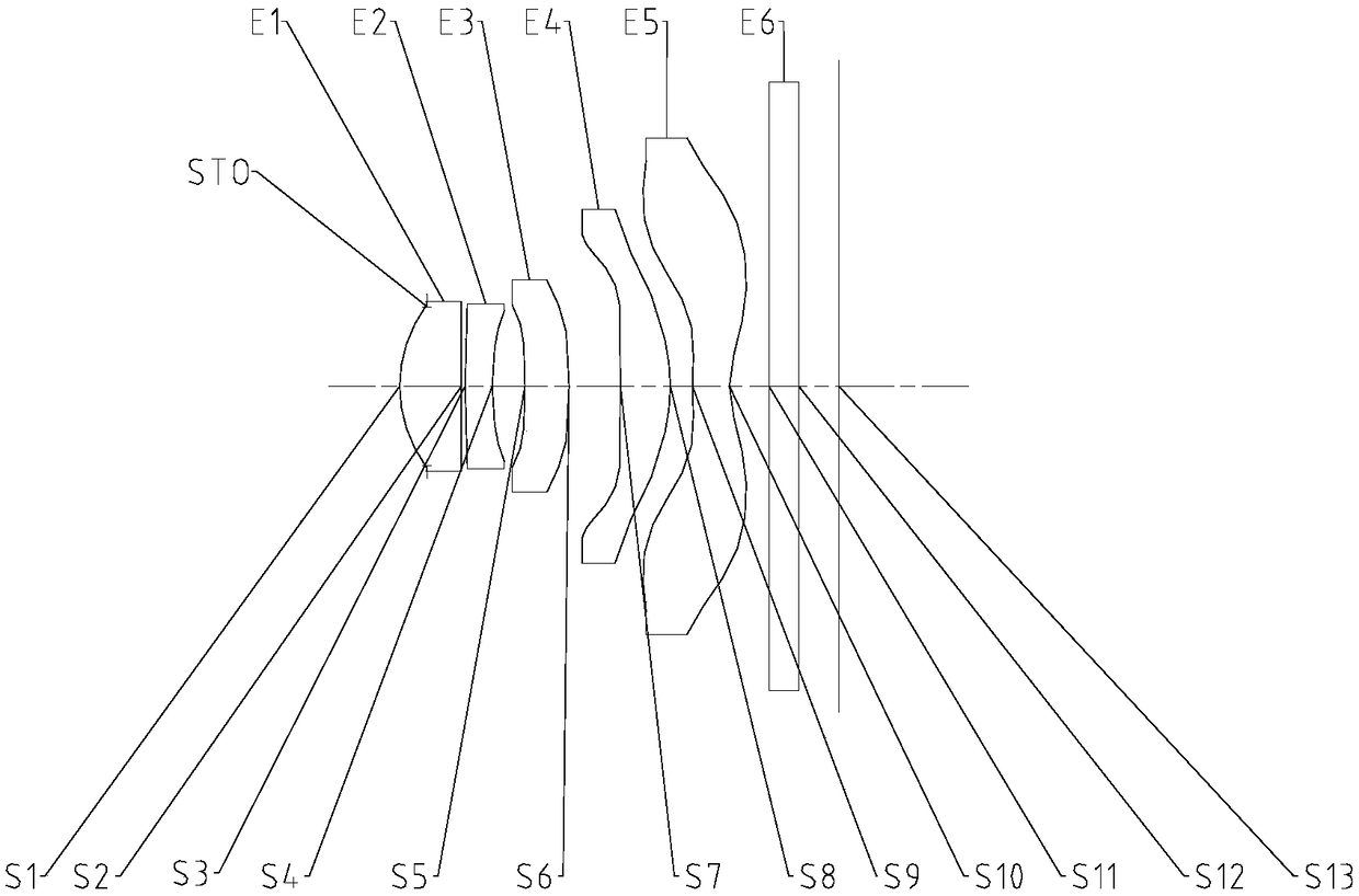
[0067] Refer to the following Figure 1 to Figure 2C An imaging lens group according to Embodiment 1 of the present application will be described. figure 1 A schematic structural diagram of the camera lens group according to Embodiment 1 of the present application is shown.
[0068] Such as figure 1 As shown, the imaging lens group according to the exemplary embodiment of the present application includes in sequence along the optical axis from the object side to the image side: a diaphragm STO, a first lens E1, a second lens E2, a third lens E3, and a fourth lens E4 , the fifth lens E5, the filter E6 and the imaging surface S13.
[0069] The first lens E1 has positive refractive power, its object side S1 is convex, and its image side S2 is concave. The second lens E2 has negative refractive power, its object side S3 is convex, and its image side S4 is concave. The third lens E3 has positive refractive power, its object side S5 is concave, and its image side S6 is convex. ...
Embodiment 2
[0096] Refer to the following Figure 3 to Figure 4C An imaging lens group according to Embodiment 2 of the present application will be described. In this embodiment and the following embodiments, for the sake of brevity, descriptions similar to those in Embodiment 1 will be omitted. image 3 A schematic structural diagram of the camera lens group according to Embodiment 2 of the present application is shown.
[0097] Such as image 3 As shown, the imaging lens group according to the exemplary embodiment of the present application includes in sequence along the optical axis from the object side to the image side: a diaphragm STO, a first lens E1, a second lens E2, a third lens E3, and a fourth lens E4 , the fifth lens E5, the filter E6 and the imaging surface S13.
[0098] The first lens E1 has positive refractive power, its object side S1 is convex, and its image side S2 is concave. The second lens E2 has negative refractive power, its object side S3 is convex, and its im...
Embodiment 3
[0112] Refer to the following Figure 5 to Figure 6C An imaging lens group according to Embodiment 3 of the present application is described. Figure 5 A schematic structural diagram of a camera lens group according to Embodiment 3 of the present application is shown.
[0113] Such as Figure 5As shown, the imaging lens group according to the exemplary embodiment of the present application includes in sequence along the optical axis from the object side to the image side: a diaphragm STO, a first lens E1, a second lens E2, a third lens E3, and a fourth lens E4 , the fifth lens E5, the filter E6 and the imaging surface S13.
[0114] The first lens E1 has positive refractive power, its object side S1 is convex, and its image side S2 is concave. The second lens E2 has negative refractive power, its object side S3 is convex, and its image side S4 is concave. The third lens E3 has positive refractive power, its object side S5 is concave, and its image side S6 is convex. The fo...
PUM
 Abstract
Description
Claims
Application Information