
Cable-twisting device

A twisted wire and cable technology, which is applied in the field of cable processing equipment, can solve the problems of inaccurate control of pitch, unstable power or information transmission process, etc., and achieve the effect of improving twisting quality and stability

Active Publication Date: 2018-12-18
HUAINAN WENFENG AEROSPACE CABLE CO LTD
View PDF7 Cites 3 Cited by
  • Summary
  • Abstract
  • Description
  • Claims
  • Application Information

AI Technical Summary

Problems solved by technology

Compared with the previous manual stranding, the existing cable stranding machine can increase the stranding rate and the tightness of the wire stranding, but the pitch during the stranding process cannot be precisely controlled, resulting in unstable power or information transmission.

Method used


Image

  • Cable-twisting device
  • Cable-twisting device
  • Cable-twisting device

Examples


Embodiment 1

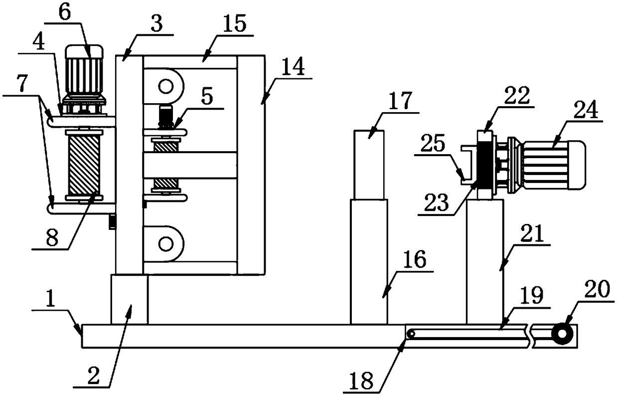
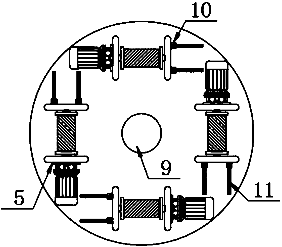
[0029] The present invention provides such as Figure 1-9 The shown cable twisting device includes a base 1, the top of the base 1 is provided with a first fixed pallet 2, and the top of the first fixed pallet 2 is vertically provided with a fixed plate 3, and the fixed plate 3 One side is provided with a first guide wire mechanism 4 and the other side is provided with a second guide wire mechanism 5, the first guide wire mechanism 4 and the second guide wire mechanism 5 both include a limiting plate group 7, and the limiting plate group 7 Set vertically between the fixed plate 3, the limiting plate group 7 is composed of a left side plate and a right side plate, the two ends of the outer side of the left side plate are fixed with locking blocks 10 and the outer center of the right side plate is provided with The first motor 6, a wire barrel 8 is arranged between the left side plate and the right side plate, the center position of the wire barrel 8 is provided with a rotating ...

Embodiment 2

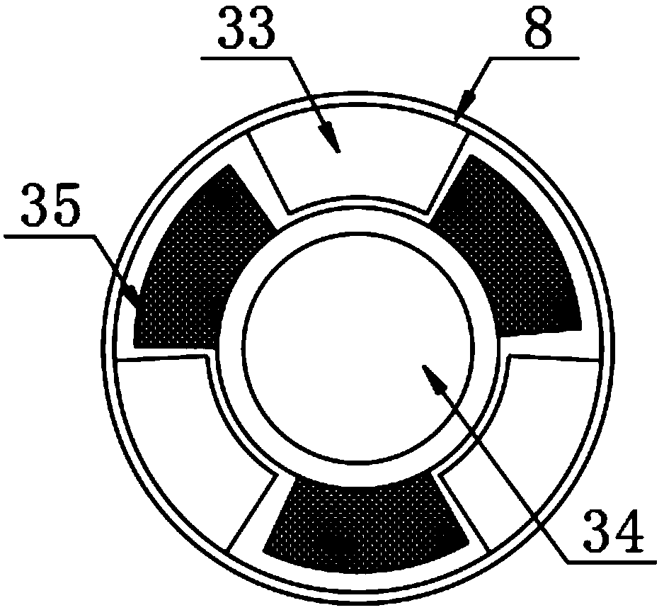
[0036] Further, in the technical solution of Embodiment 1, a gear 35 is fixedly sleeved on the rotating rod 34, and a second gear 33 is arranged inside the wire barrel 8, and the gear 35 meshes with the second gear 33 , when the cable on the spool 8 is used up, you only need to loosen the locking screw on the locking block 10, and then slide the left side plate along the strip thread groove 11 until it is far away from the rotating rod 34 When a certain distance is reached, the spool 8 is removed, and the spool 8 wrapped with a cable is replaced to be set on the rotating rod 34, and then the left side plate is used to limit the spool 8 to carry out the next round. stranded wire.

[0037] Further, in the technical solution of Embodiment 1, there are rollers 26 movably connected in the groove of the limiting groove 15 through connecting rods, and there are multiple rollers 26, and the plurality of rollers 26 are evenly distributed in the limiting groove 15, the inner wall of th...


PUM


Abstract

The invention relates to a cable twisting device Including base, A first fixed bracket is arranged on the top of the base, A fixing plate is vertically arranged on the top of the first fixing bracket,One side of the fixing plate is provided with a first wire mechanism, and the other side is provided with a second wire mechanism. The first wire mechanism and the second wire mechanism both comprisea finite position plate group. The position limiting plate group is vertically arranged between the position limiting plate group and the fixing plate, and the position limiting plate group is composed of a left side plate and a right side plate. By passing the side cable to be stranded through the limiting groove and the wire hole on the wire plate in turn, and the center cable passes through the center position of the stranded tube, and the side cable passes through the conductor groove formed between the adjacent spiral guide strips, and then the pitch in the stranding process can be ensured to be a fixed value by using the turntable with the fixing clip in the rotating process and the stranded tube, so as to greatly improve the twisting quality of the cable.

Description

technical field [0001] The invention relates to the field of cable processing equipment, in particular to a cable twisting device. Background technique [0002] A cable is a wire made of one or more mutually insulated conductors and an outer insulating layer, and transmits power or information from one end to the other. Cables are usually multiple or multiple groups (at least two in each group) twisted together, each group of wires are insulated from each other, and twisted around a center. Compared with the previous manual stranding, the existing cable stranding machine can increase the stranding speed and the tightness of the wire stranding, but the pitch during the stranding process cannot be precisely controlled, resulting in unstable power or information transmission. [0003] Therefore, it is necessary to invent a cable twisting device to solve the above problems. Contents of the invention [0004] The purpose of the present invention is to provide a cable strandin...

Claims


Application Information

Patent Timeline
IPC IPC(8): H01B13/02
CPCH01B13/0207
Inventor 徐文利王迟龙蒋华平刘陆赵莉邹良龙叶桦徐文峰杨涛
Owner HUAINAN WENFENG AEROSPACE CABLE CO LTD
Learn More