Centralized rotary creel stand

A rotary pay-off and centralized technology, applied in the field of pay-off racks, can solve problems such as complex structure of pay-off racks, limited production efficiency, and extended stranding speed, so as to reduce stranding distance, improve stranding quality, and improve The effect of traction speed

Active Publication Date: 2012-08-01
HEFEI SMARTER TECH GROUP CORP
View PDF0 Cites 0 Cited by
  • Summary
  • Abstract
  • Description
  • Claims
  • Application Information

AI Technical Summary

Problems solved by technology

[0002] The currently used rotary pay-off frame of the disc cable forming machine adopts such as figure 1 The decentralized structure shown, figure 1 The wire reels shown in , including A wire reel 11, B wire reel 12, C wire reel 13 and D wire reel 14, are on the same floor plane, that is, they are distributed on the ground according to front, back, left and right. This type of wire reel distribution covers a large area, the production line is long, and the twisting point is far away, so the twisting speed is prolonged and the improvement of production efficiency is greatly limited. Not only that, the pay-off frame of each wire reel in this decentralized structure Complex structure and high cost

Method used


Image

  • Centralized rotary creel stand
  • Centralized rotary creel stand
  • Centralized rotary creel stand

Examples


Embodiment Construction

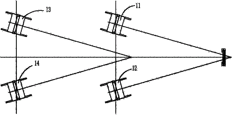
[0020] The setting of the pay-off frame is a double-layer frame structure with an upper frame and a lower frame parallel to each other concentrated on the same axial position; each wire frame is distributed on the upper frame and the lower frame respectively to form the spatial distribution of the wire frame; In the upper frame and the lower frame, each wire reel in the same layer is centered on the outlet of the floor, and the axes of each wire reel are fan-shaped to each other, and the wire reels in different layers are not in the same vertical position. On a straight plane, this form can effectively avoid the interference between the wire reels.

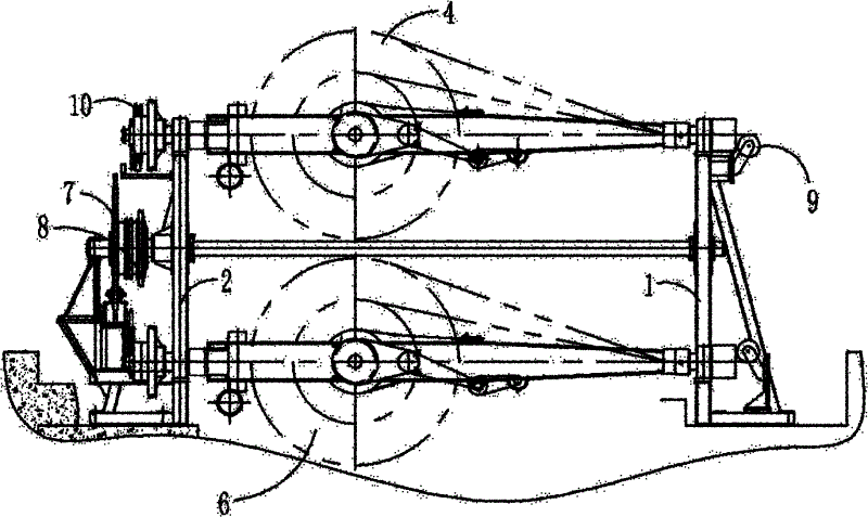
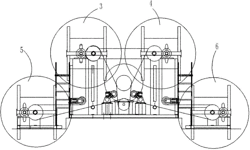
[0021] see figure 2 , image 3 and Figure 4 , in the present embodiment, setting pay-off frame is the double-layer structure that has upper shelf and lower shelf that is made up of front supporting frame 1 and rear supporting frame 2 jointly, the upper layer left wire tray frame 3 and the upper layer right wire tray in the upp...


PUM


Abstract

The invention discloses a centralized rotary creel stand which is characterized in that the arranged creel stand is a double-layer rack structure which is centralized at the same one axial position and is provided with an upper layer rack and a lower layer rack which are parallel with each other, and all spool holders are distributed on the upper layer rack and the lower layer rack. The inventionhas small occupied area, low cost and simple structure and can effectively improve the stranding quality of a wire core and improves the production efficiency.

Description

technical field [0001] The invention relates to a pay-off stand used in cable production, more specifically a pay-off stand mainly used in the twisting of large-section and long-length power cables. Background technique [0002] The currently used rotary pay-off frame of the disc cable forming machine adopts such as figure 1 The decentralized structure shown, figure 1 The wire reels shown in , including A wire reel 11, B wire reel 12, C wire reel 13 and D wire reel 14, are on the same floor plane, that is, they are distributed on the ground according to front, back, left and right. This type of wire reel distribution covers a large area, the production line is long, and the twisting point is far away, so the twisting speed is prolonged and the improvement of production efficiency is greatly limited. Not only that, the pay-off frame of each wire reel in this decentralized structure The structure is complicated and the cost is high. Contents of the invention [0003] The ...

Claims


Application Information

Patent Timeline
Patent Type & Authority Patents(China)
IPC IPC(8): H01B13/02B65H49/18B65H49/32
Inventor 岳光明谢警孙正云范杨刘国军
Owner HEFEI SMARTER TECH GROUP CORP
Why Eureka
Try Eureka