
A deep-hole machine tool shaft-torsional compound vibration test device

A technology of composite excitation and experimental equipment, applied in the direction of driving equipment, feeding equipment, measuring equipment, etc., can solve problems such as insufficient precision, difficulty in maintaining amplitude, and improvement of deep hole processing quality to a higher level, so as to adjust the speed and torque Simple, reduced amplitude attenuation, and eliminated adverse effects

Active Publication Date: 2019-07-12
东台城东科技创业园管理有限公司
View PDF8 Cites 0 Cited by
  • Summary
  • Abstract
  • Description
  • Claims
  • Application Information

AI Technical Summary

Problems solved by technology

[0005] 1. Most of them are ultrasonic excitation instruments. This type of exciter is bulky, expensive, and the experimental form is single, which is not suitable for experimental research.
[0006] 2. Most of them are low-frequency exciters, the precision is not enough, it is difficult to maintain a stable amplitude, and the quality of deep hole processing is greatly reduced
[0007] 3. Most of the existing vibration excitation devices are mainly axial vibration, and the excitation form is single
However, when processing materials such as titanium alloys, the quality and efficiency of deep hole processing are inevitably affected
It is difficult to improve the quality of deep hole processing by traditional cutting methods. At the same time, the continuous development of my country's machinery manufacturing industry has also put forward more stringent requirements for deep hole processing accuracy and surface quality.

Method used


Image

  • A deep-hole machine tool shaft-torsional compound vibration test device
  • A deep-hole machine tool shaft-torsional compound vibration test device
  • A deep-hole machine tool shaft-torsional compound vibration test device

Examples


Embodiment Construction

[0056] The present invention will be further described in detail below in conjunction with the accompanying drawings and specific preferred embodiments.

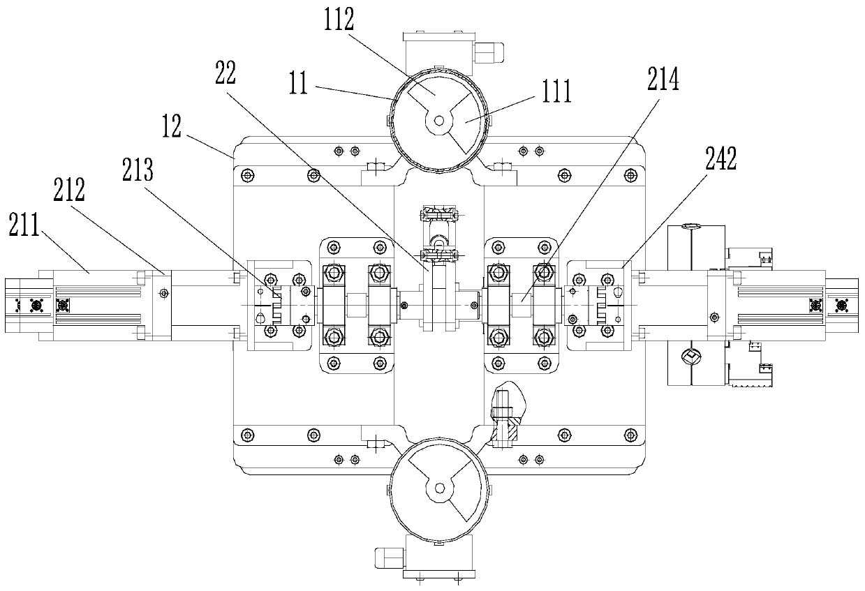
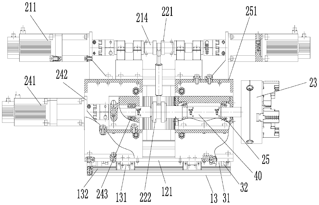
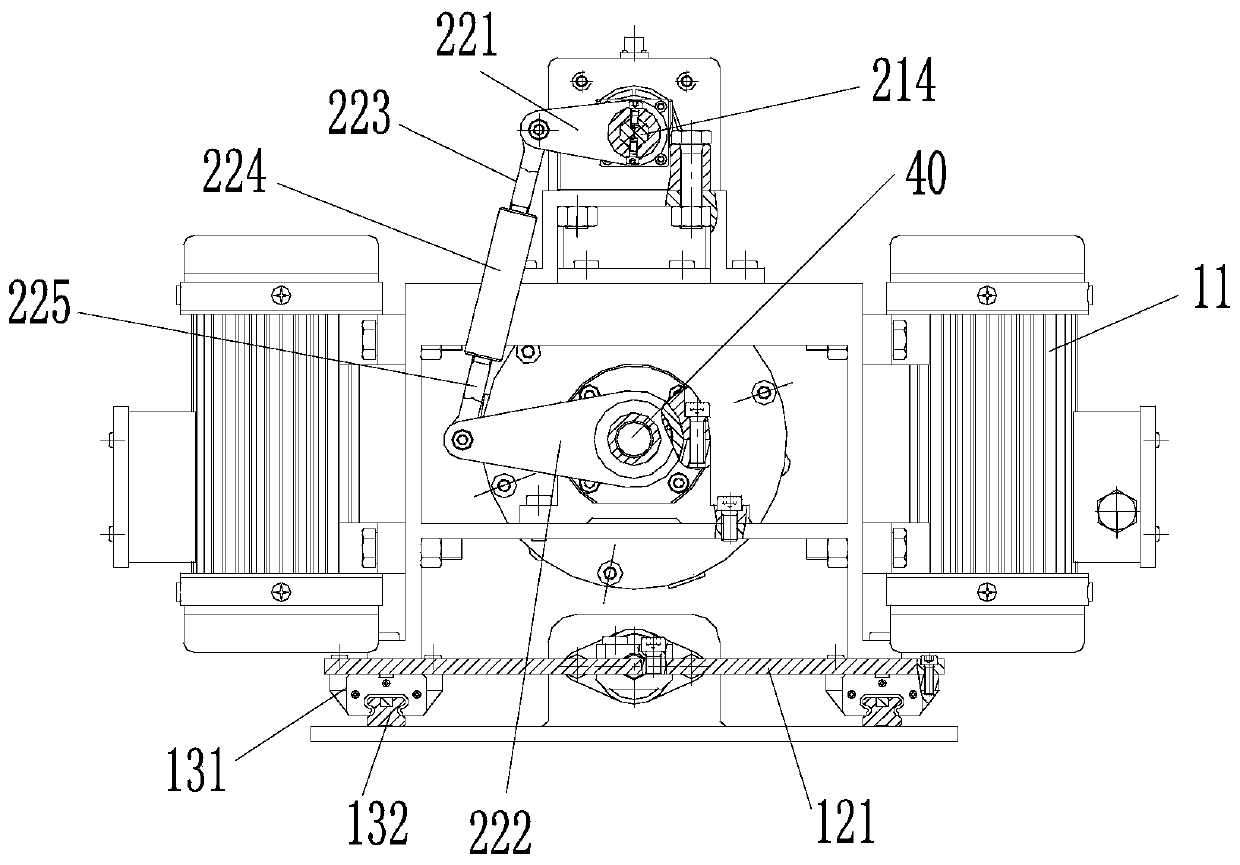
[0057] Such as figure 1 and figure 2 As shown, an axial-torsional composite excitation device for deep hole machine tools includes an axial excitation unit, a torsion unit, a real-time amplitude measurement and display unit, and a body shock absorption unit.

[0058] The axial vibration unit is used for axially vibrating the workpiece to be machined for deep holes. The axial vibration unit includes a frequency converter, a vibration motor 11, a vibrating body 12 and a workpiece axial fixing assembly.

[0059] There are two vibrating motors, which are symmetrically arranged on both sides of the vibrating body, and the centroids of the two vibrating motors coincide with that of the vibrating body.

[0060] The bottom of the vibrating body is a vibration platform 121, and the vibration platform is horizontally slidably conn...


PUM


Abstract

The invention discloses a deep hole machine tool spindle-torsion compound excitation experimental device, which comprises an axial excitation unit, a torsion unit and an amplitude real-time measurement and display unit. The axial excitation unit comprises frequency converters, vibration motors, a vibrating participant body and a workpiece axial fixing component; the two vibration motors can vibrate synchronously, and each vibration motor is connected with the corresponding frequency converter; two angle-adjustable weighting blocks are arranged at each of the both ends of the motor shaft of each vibration motor; the torsion unit includes a unidirectional torsion assembly, a periodic reciprocating torsion assembly and a workpiece torsion clamping assembly; the amplitude real-time measurementand display unit is used for detecting and displaying the axial amplitude of the axial excitation unit in real time. The deep hole machine tool spindle-torsion compound excitation experimental devicecan realize switching of three different vibration modes, and can improve the drilling efficiency and machining quality of a deep hole. Under the condition of maintaining the normal feed of a gun-drill, a workpiece is fixed on an excitation table and vibrates axially with the excitation table. In addition, the workpiece can also do reciprocating torsion motions, which meets the design requirementof an experimental platform.

Description

technical field [0001] The invention relates to the field of deep hole processing, in particular to a deep hole machine tool shaft-torsion compound excitation experiment device. Background technique [0002] With the development of industrial technology, deep hole processing has been widely used in energy (petroleum mining, coal, electric power), aerospace, metallurgy, automobile, chemical and other fields, and its proportion is becoming more and more prominent. At present, hole processing accounts for about 30% of the entire mechanical processing system, of which more than 40% of hole processing belongs to the category of deep hole processing, and 22% is for the processing of solid materials, and relevant data show that the output of drills accounts for about 60% of the total output of cutting tools. [0003] In the 1950s, the concept of vibration drilling was first proposed by Professor Junichiro Kumabe. Compared with ordinary drilling, vibration drilling has full advant...

Claims


Application Information

Patent Timeline
Patent Type & Authority Patents(China)
IPC IPC(8): B23B41/02B23B45/02B23Q5/10B23Q5/28G01M7/02
CPCB23B41/02B23B45/02B23Q5/10B23Q5/28G01M7/022
Inventor 李亮薛虎朱奔驰刘鹏石启鹏
Owner 东台城东科技创业园管理有限公司
Learn More