
Transmission rod for door and window attachment

A transmission rod and accessory technology, applied in the field of transmission rods, can solve the problems of very high cutting precision and range requirements of transmission rods, limited cutting length, low degree of automation, etc., so as to improve work coordination, efficient and precise cutting, and improve work efficiency. The effect of efficiency

Inactive Publication Date: 2018-12-21
王磊
View PDF0 Cites 0 Cited by
  • Summary
  • Abstract
  • Description
  • Claims
  • Application Information

AI Technical Summary

Problems solved by technology

[0002] Doors and windows use transmission rods to connect various accessories to realize the functions of doors and windows. Therefore, transmission parts are very important for doors and windows. At present, there are many types of doors and windows in general use. In addition, some doors and windows can be customized according to user needs, and the length of the transmission rod depends on the size of the doors and windows. This puts very high requirements on the cutting accuracy and range of the transmission rod length of the manufacturer. The traditional transmission rod cutting needs to be manually adjusted, and the cutting length is limited, the degree of automation is low, and it is laborious. This equipment effectively solves this problem.

Method used


Image

  • Transmission rod for door and window attachment
  • Transmission rod for door and window attachment
  • Transmission rod for door and window attachment

Examples


Embodiment Construction

[0020] All features disclosed in this specification, or steps in all methods or processes disclosed, may be combined in any manner, except for mutually exclusive features and / or steps.

[0021] Any feature disclosed in this specification (including any appended claims, abstract and drawings), unless expressly stated otherwise, may be replaced by alternative features which are equivalent or serve a similar purpose. That is, unless expressly stated otherwise, each feature is one example only of a series of equivalent or similar features.

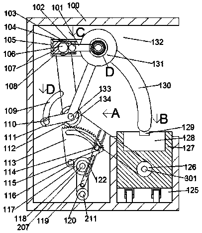
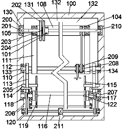
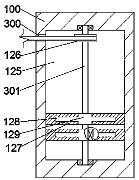
[0022] Such as Figure 1-6 As shown, the transmission rod of a door and window accessory of the present invention includes a box body 100, a working groove 132 is fixed inside the box body 100, a driving motor 211 is fixed on the lower end wall of the working groove 132, and the driving motor The front and rear output shafts of 211 are rotationally connected with the front and rear end walls of the working tank 132. The outer surface of the o...


PUM


Abstract

The invention discloses a transmission rod of a door and window attachment, comprising a box body. A working slot is fixed in the box body. A driving motor is fixed on the lower end wall of the working slot. The front-rear output shaft of the driving motor is rotationally coupled with the front and rear end walls of the working slot. A driving gear is fixed on the outer surface of the output shaftof the driving motor. Front-rear symmetrical side cavities with downward facing openings are fixed in the working slot. A penetration rod is connected to the end wall, far away from the working slot,of the working slot in a running fit manner. The penetration rod penetrates the side cavity in a rotating manner. The outer surface of the penetration rod is fixed with a driven gear located in the side cavity and a side wheel located in the working slot. Sliding point away from the center of the side wheel is fixed to the end surface, near to the working slot, of the side wheel. The transmissionrod for the door and window attachment has simple structure and is convenient to use. The automated working mode realizes efficient and precise cutting of the transmission rod, expands the range of the cutting of the equipment, improves the diversification of the equipment and improves work efficiency.

Description

technical field [0001] The invention relates to the field of hardware, in particular to a transmission rod for door and window accessories. Background technique [0002] Doors and windows use transmission rods to connect various accessories to realize the functions of doors and windows. Therefore, transmission parts are very important for doors and windows. At present, there are many types of doors and windows in general use. In addition, some doors and windows can be customized according to user needs, and the length of the transmission rod depends on the size of the doors and windows. This requires very high requirements for the cutting accuracy and range of the transmission rod length of the manufacturer. The traditional transmission rod cutting needs to be manually adjusted, and the cutting length is limited, the degree of automation is low, and it is laborious. This equipment effectively solves this problem. Contents of the invention [0003] The object of the present...

Claims


Application Information

Patent Timeline
Patent Type & Authority Applications(China)
IPC IPC(8): B23Q1/25B23Q15/24
CPCB23Q1/25B23Q15/24
Inventor 王磊
Owner 王磊
Learn More