
Environment-friendly engine

An environment-friendly engine technology, applied to engine components, machines/engines, mechanical equipment, etc., can solve the problems of environment-friendly engine vibration, increase the burden of arrangement, shorten the reaction distance, etc., to achieve efficient power improvement and easy installation , the effect of reducing the occupied area

Inactive Publication Date: 2018-12-21
宁波鄞州康圣机械科技有限公司
View PDF0 Cites 4 Cited by
  • Summary
  • Abstract
  • Description
  • Claims
  • Application Information

AI Technical Summary

Problems solved by technology

Environmentally friendly engines are the most commonly used machinery for converting chemical energy into mechanical energy. Usually, manufacturers increase power and shorten reaction distances in order to meet national environmental protection requirements, which will cause problems such as vibration of environmentally friendly engines. At the present stage, the arrangement of multiple cylinders takes up a lot of space and increases the burden. Therefore, a tool that can alleviate the vibration and change the arrangement of cylinders has become an inevitable trend in today's development. A new environment-friendly engine that can solve the above-mentioned problems is explained in the present invention.

Method used


Image

  • Environment-friendly engine
  • Environment-friendly engine
  • Environment-friendly engine

Examples


Embodiment Construction

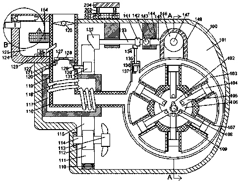
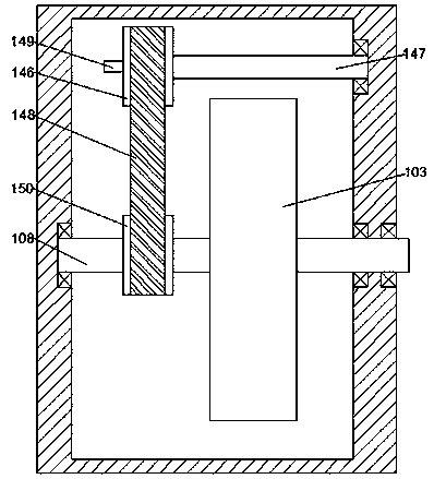
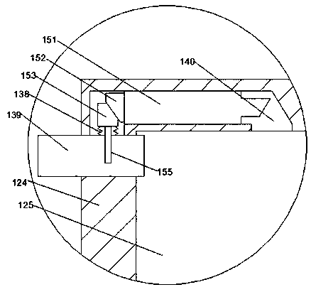
[0016] Such as Figure 1-Figure 3 As shown, the environment-friendly engine of the present invention includes a fuselage 100 and a first cavity 101 arranged in the fuselage 100, the inner wall of the right end of the first cavity 101 is fixedly connected with a circular cylinder 103, and the circular cylinder 103 The inner circumference of the cylinder 103 is provided with equidistantly distributed piston chambers 107, the piston chamber 107 is slidably connected with a piston 108, and the near center end of the piston 108 is fixedly connected with a piston push rod 105, and the piston push rod 105, The circular cylinder 103 is provided with an internal tooth chamber 109 located at the center of the circle, and the internal tooth chamber 109 is rotatably connected with an output shaft 108 extending forward and backward. 103 rear end of the first sprocket 150, the output shaft 108 is sleeved with a disc 106, the disc 106 is fixedly connected with a first fixed tip 102 located a...


PUM


Abstract

The invention discloses an environment-friendly engine, comprising an engine body and a first cavity arranged in the engine body. A circular cylinder is fixedly connected with the inner wall of the right end of the first cavity. Piston cavities distributed equally are circumferentially arranged in the circular cylinder. Pistons are connected with the piston cavities in a sliding fit mode. Piston push rods are fixedly connected with the proximal ends of the circle centers of the pistons. An internal tooth chamber located at the circle center is arranged in the circular cylinder. An output shaftextending back and forth is connected with the internal tooth chamber in a rotating fit mode. A first chain wheel located at the rear end of the circular cylinder is arranged on the output shaft. A disc is sleeved on the output shaft. A first fixing pin located at the circle center is fixedly connected with the disc. A hinge is arranged between the first fixing pin and the output shaft for connection. The environment-friendly engine is high in linkage, and an optimal oil-gas ratio is achieved by driving a valve to open and close through the output shaft, and the occupied area is reduced by the arrangement mode of the annular cylinder.

Description

technical field [0001] The invention relates to the technical field of power energy, in particular to an environment-friendly engine. Background technique [0002] Human beings have never stopped exploring and applying energy since ancient times. Environmentally friendly engines are the most commonly used machinery for converting chemical energy into mechanical energy. Usually, manufacturers increase power and shorten reaction distances in order to meet national environmental protection requirements, which will cause problems such as vibrations in environmentally friendly engines. At the current stage, the arrangement of multiple cylinders takes up a lot of space and increases the burden. Therefore, a tool that can alleviate the vibration and change the arrangement of cylinders has become an inevitable trend of development. A new environment-friendly engine that can solve the above problems is explained by the present invention. . Contents of the invention [0003] The t...

Claims


Application Information

Patent Timeline
Patent Type & Authority Applications(China)
IPC IPC(8): F02B75/22F02B61/06F02B75/40F02M5/00
CPCF02B75/1896F02B61/06F02B75/222F02B75/40F02B2075/1824F02M5/00
Inventor 汤晓健
Owner 宁波鄞州康圣机械科技有限公司
Learn More