
A fan housing

A closed fan and casing technology is applied in the field of closed fan casing, which can solve the problems of unfavorable service life of the closed fan and improving the degree of wear of fan blades.

Active Publication Date: 2020-07-24
安徽省碧绿春生物科技有限公司
View PDF5 Cites 0 Cited by
  • Summary
  • Abstract
  • Description
  • Claims
  • Application Information

AI Technical Summary

Problems solved by technology

In this way, although the air-closing effect of the closed fan is guaranteed, the fan blades always rub against the inner wall of the casing during the rotation of the impeller, which greatly increases the wear of the fan blades, which is not conducive to the service life of the closed fan.

Method used


Image

  • A fan housing
  • A fan housing

Examples


Embodiment 1

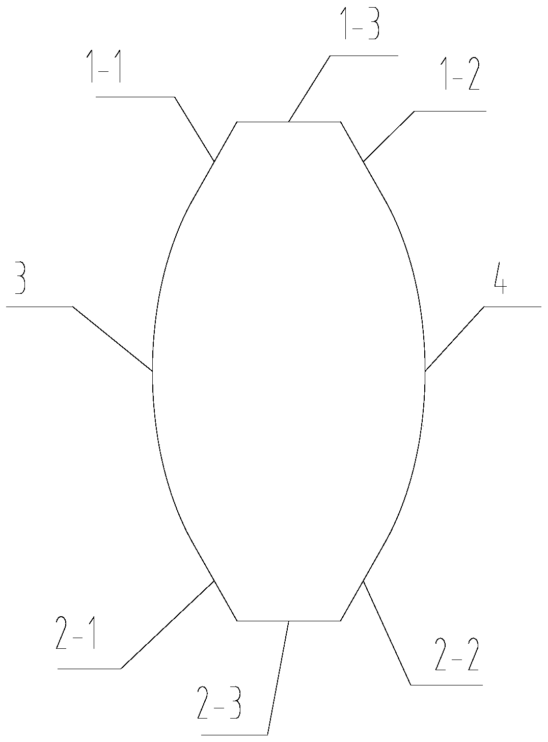
[0025] In this embodiment, the top surface 1 is composed of a first plane 1-1, a second plane 1-2 and a third plane 1-3, and the bottoms of the first plane 1-1 and the second plane 1-2 are respectively connected to the first The tops of the arc surface 3 and the second arc surface 4 are respectively tangent to the first arc surface 3 and the second arc surface 4, and the third plane 1-3 is arranged horizontally, and its two sides are respectively connected to the first plane 1-1 and the second arc surface. On the top of the second plane 1-2, the feed inlet is arranged on the third plane.

[0026] The bottom surface 2 is composed of the fourth plane 2-1, the fifth plane 2-2 and the sixth plane 2-3, and the tops of the fourth plane 2-1 and the fifth plane 2-2 respectively connect the first arc surface 3 and the second arc surface. The bottom of the arc surface 4 is tangent to the first arc surface 3 and the second arc surface 4 respectively, the sixth plane 2-3 is set horizontal...

Embodiment 2

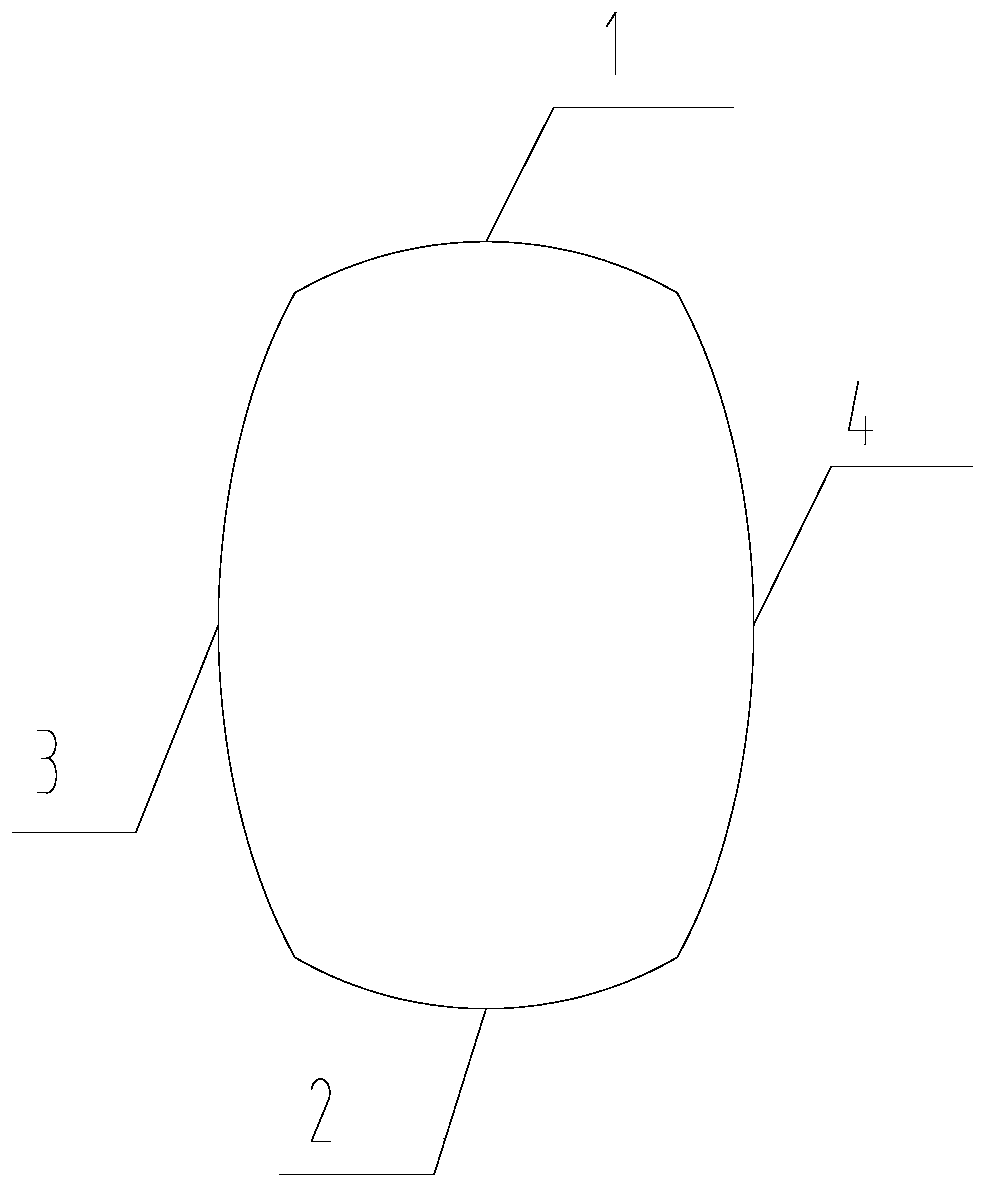
[0029] In this embodiment, the projection of the top surface 1 and / or the bottom surface 2 on the end surface is located on a circle B with a radius equal to L1, which is beneficial to reducing the volume of the entire housing.

Embodiment 3

[0031] In this embodiment, the projection of the top surface 1 and / or the bottom surface 2 on the end surface is located on the ellipse A. Further, the projections of the top surface 1 , the bottom surface 2 , the first arc surface 3 and the second arc surface 4 on the end surface form a complete ellipse A. In this way, the entire shell forms an elliptical cylindrical structure, which is convenient for processing and forming.


PUM


Abstract

The invention provides a rotary feeder shell body. The shell body is of a sealing structure composed of a surrounding surface and two end surfaces, the two end surfaces are parallel to each other, andprojections of the surrounding surface on the end surfaces are of a closed structure; the surrounding surface is composed of a top surface, a bottom surface, a first arc surface and a second arc surface, and the projections of the top surface, the bottom surface, the first arc surface and the second arc surface on the end surfaces are of a linear structure; the first arc surface and the second arc surface are of the symmetric structure, and are arranged symmetrically with concave surfaces of the first arc surface and the second arc surface face with each other, the top of the bottom surface is connected with the bottom of the first arc surface and the bottom of the second arc surface, and the bottom of the top surface is connected with the top of the first arc surface and the top of the second arc surface. The rotary feeder shell body is indeed the structure with which the periphery of rotating tracks of an impeller is coated and which partially overlaps with the rotating tracks of the impeller. In this way, air closing performance of a rotary feeder is guaranteed, a friction route between fan blades and the shell body is reduced, therefore friction damage between the fan blades and the shell body is reduced; and friction force between the fan blades and the shell body is reduced, so that the friction loss is reduced.

Description

technical field [0001] The invention relates to the technical field of closed fans, in particular to a closed fan casing. Background technique [0002] The closed fan is composed of a casing and an impeller installed inside the casing, and the impeller is composed of a rotating shaft and fan blades installed on the rotating shaft and rotating with the rotating shaft. The fan blade cooperates with the rotating shaft to divide the interior of the casing into fan-shaped spaces that are equal to the number of fan blades along the circumference of the rotating shaft. The inlet and outlet of the casing are located in different fan-shaped spaces, and the fan-shaped space where the inlet is located and The fan-shaped space where the discharge port is located is isolated by the fan blades in any state, so as to ensure the isolation of the feed port and the discharge port. [0003] At present, the closed fans appearing on the market have a cylindrical shell structure. During the rota...

Claims


Application Information

Patent Timeline
Patent Type & Authority Patents(China)
IPC IPC(8): F04D29/40
CPCF04D29/403
Inventor 董传宁杨银
Owner 安徽省碧绿春生物科技有限公司
Learn More