Multi-section telescopic rod

A technology of telescopic rods and section rods, which is applied to the connection of rods, slender elements, connecting components, etc., can solve the problems of increasing the shaking range of multi-section telescopic rods, the superimposed increase of slight shaking ranges, and large swinging ranges, etc., to achieve fast Effective positioning direction and in-position operation, improved mechanical properties, and reduced swing amplitude

Inactive Publication Date: 2018-12-21
赵丽红
View PDF0 Cites 3 Cited by
  • Summary
  • Abstract
  • Description
  • Claims
  • Application Information

AI Technical Summary

Problems solved by technology

[0003] Under the existing production technology of telescopic rods, there is inevitably a gap between the thinner outer wall of the front segment rod and the thicker inner wall of the adjacent rear segment rod for assembly, so that the front segment rod during use There is a slight shaking in the adjacent rear section pole. When it is necessary to use more sections of telescopic poles for extension work, as the number of sections of the telescopic poles continues to increase, the slight shaking range will continue to superimpose and increase. Under the influence of external forces such as hand operation and wind, the swing range is relatively large and difficult to control, especially in the process of high-altitude cleaning, etc., it is easy to accidentally collide with other objects, especially valuables. As the number of segments continues to increase, the center of gravity of the extended telescopic rod increases accordingly, and the rod body is bent and deformed under the action of gravity, which further increases the shaking range of the multi-section telescopic rod during actual use, making it more difficult to control, giving It brings great troubles to users. This is a technical difficulty that has not been overcome by those skilled in the art for many years and needs to be solved urgently.

Method used


Image

  • Multi-section telescopic rod
  • Multi-section telescopic rod
  • Multi-section telescopic rod

Examples


Embodiment Construction

[0039] The present invention will be further described below in conjunction with the accompanying drawings and specific embodiments, so as to help understand the content of the present invention. The methods used in the present invention are conventional methods unless otherwise specified; the raw materials and devices used are conventional commercially available products unless otherwise specified.

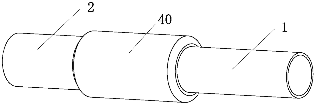
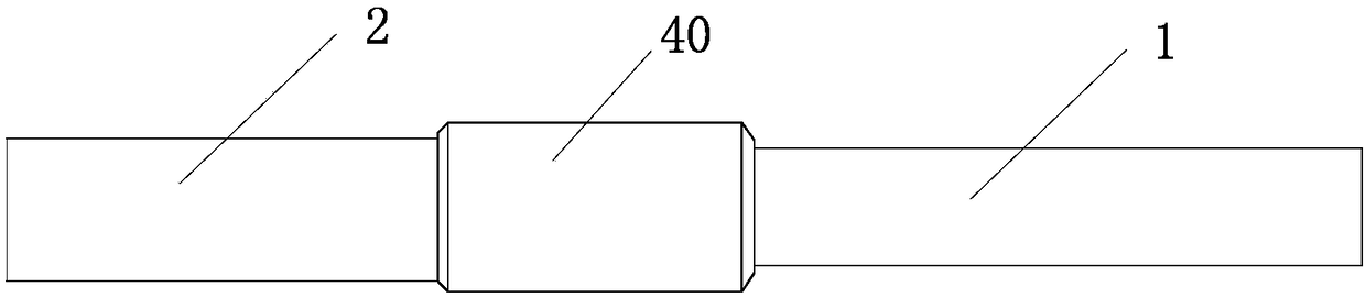
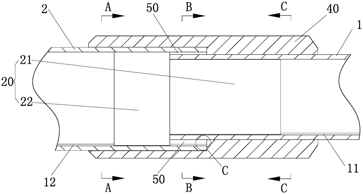
[0040] Depend on Figure 1-Figure 7 As shown, the present invention provides a multi-section telescopic rod. When a multi-section telescopic rod needs to be used for elongation work, the user stretches a plurality of multi-section telescopic rods, and now arbitrarily selects two adjacent ones. Take the joint bar as an example, which is provided with two joint bars, one joint 20 and one connecting lock piece 40 . The joint bar is tubular, which can be a circular tubular structure. The joint bar is provided with a first joint bar 1 and a second joint bar 2. From front to back, the...


PUM


Abstract

The invention provides a multi-section telescopic rod. The multi-section telescopic rod solves the technical problem that in the case of an existing multi-section telescopic rod, when multiple sections of the telescopic rod need to be used for the extension operation, a rod body of the telescopic rod is relatively large in swinging amplitude under the action of external force and then is not easyto control. The multi-section telescopic rod is provided with n sectional rods, n-1 joints and n-1 connecting lock pieces, wherein n is a positive integer not smaller than 2; and a cylindrical first locking through hole and a cylindrical second locking through hole which communicate with each other are formed in each connecting locking piece, the hole diameter of each first locking through hole isthe same as the outer diameter of the corresponding front sectional rod, moreover, each first locking through hole is connected with the outer wall of the corresponding front sectional rod in a sliding fit mode, the hole diameter of each second locking through hole is the same as the outer diameter of the corresponding rear sectional rod adjacent to the corresponding front sectional rod, and eachsecond locking through hole is connected with the outer wall of one end of the corresponding rear sectional rod adjacent to the corresponding front sectional rod in a fastening mode. The multi-section telescopic rod can be widely applied to the technical field of telescopic pipes.

Description

technical field [0001] The invention relates to the technical field of telescopic pipes, in particular to a multi-section telescopic rod. Background technique [0002] Because the telescopic rod can change its length, it is used in many fields, such as cleaning supplies, outdoor sports supplies, support supplies on ships, audio-visual photographic equipment, inspection and testing equipment, etc. When the user needs to use it, he stretches it to a certain length, and when he does not need to use it, he retracts it, which can save volume, be flexible in use, and be convenient to carry. [0003] Under the existing telescopic rod production technology, there is inevitably a gap between the thinner outer wall of the front segment rod and the thicker inner wall of the adjacent rear segment rod for assembly, so that the front segment rod There is a slight shaking in the adjacent rear section rod. When it is necessary to use more telescopic rods to extend the work, as the number o...

Claims


Application Information

Patent Timeline
Patent Type & Authority Applications(China)
IPC IPC(8): F16B7/12F16S3/00
CPCF16B7/105F16S3/00F16B2200/99
Inventor 赵丽红
Owner 赵丽红
Why Eureka
Try Eureka