Automatic high-temperature testing machine for capacitor

A technology for capacitors and testing machines, which is applied to components of electrical measuring instruments, environmental/reliability testing, instruments, etc., can solve problems such as reducing the temperature of testing machines, product impact, and increasing energy consumption, so as to reduce energy consumption and temperature The effect of stability and convenient capacitor

Pending Publication Date: 2018-12-21
HUNAN AIHUA GRP
View PDF0 Cites 2 Cited by
  • Summary
  • Abstract
  • Description
  • Claims
  • Application Information

AI Technical Summary

Problems solved by technology

However, the traditional high-temperature testing machine needs to open the door of the testing machine no matter whether it is to discharge the capacitor for testing or to take out the tested capacitor; products have an impact
When the door of the testing machine is opened, taking out or putting in the product is done manually. In this process, it is very easy to cause burns. At the same time, it takes a long time to take out the sample. The temperature in the testing machine will rise again after it drops. This increases energy consumption
There are many and mixed samples in the test oven. In order to meet the test needs, it is necessary to connect various power supplies with different voltages, frequencies and currents. Generally, there are many different capacitors connected to the same power supply, and the time to take them out for intermediate tests is different. When taking one of the samples, power-off operation is required, which will affect the test results of all products on the same test line

Method used


Image

  • Automatic high-temperature testing machine for capacitor
  • Automatic high-temperature testing machine for capacitor
  • Automatic high-temperature testing machine for capacitor

Examples


Embodiment

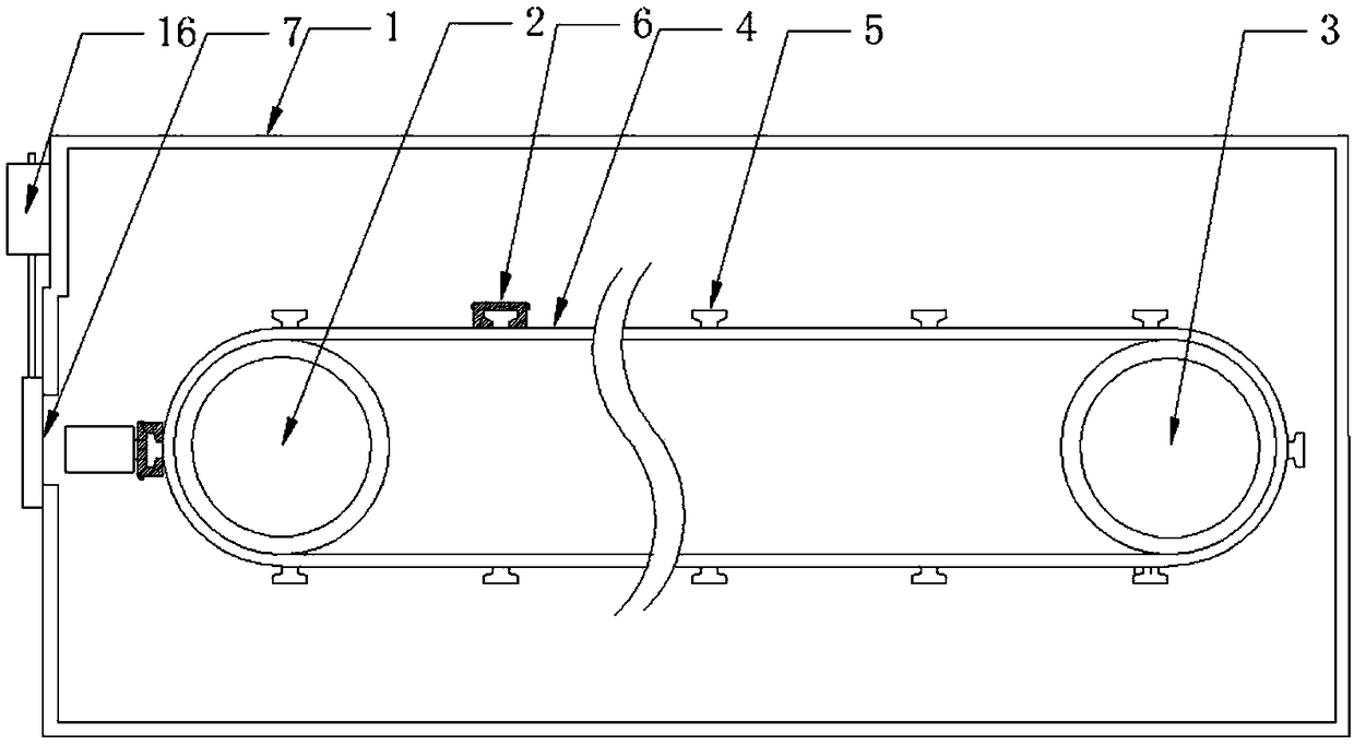
[0023] Such as figure 1 An automatic high temperature tester for capacitors is shown, including a body 1 and a door. The door is connected to the body 1. The two can form a closed cavity. The cavity is provided with a driving shaft 2 and a driven shaft 3, and the driving A belt 4 is arranged between the shaft 2 and the driven shaft 3, a base 5 is fixed on the belt 4, and a test clip 6 that can be movably connected to the capacitor on the base 5 is provided with a positive electrode conductive sheet 10 and a negative electrode conductive sheet 10 Sheet 11, the positive conductive sheet 10 on the test clip 6 is electrically connected to the driving shaft 2 through a conductive strip, and the negative conductive sheet 11 on the test clip 6 is electrically connected to the driven shaft 3 through a conductive strip; one side of the body 1 is provided There is a movable window 7.

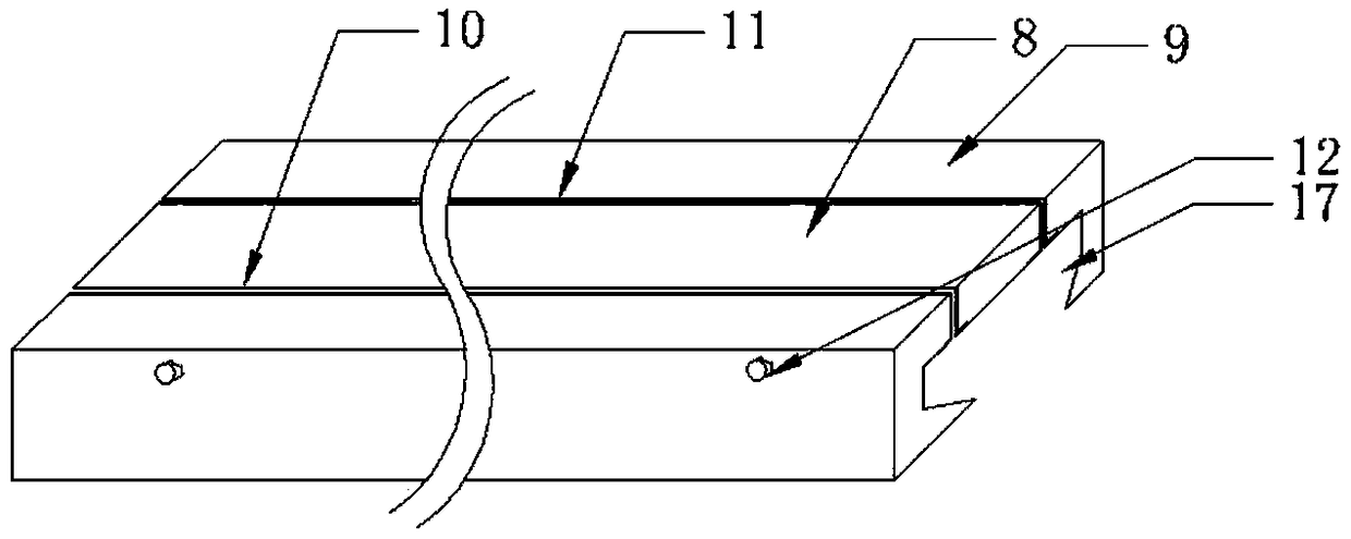
[0024] In this embodiment, such as figure 2 As shown, the test clip 6 includes an isolating block 8 and ...


PUM


Abstract

Disclosed is an automatic high-temperature testing machine for a capacitor. The automatic high-temperature testing machine comprises a machine body and a machine door, wherein the machine door is connected to the machine body, so that a closed cavity can be formed; a driving shaft and a driven shaft are arranged in the cavity; a belt is arranged between the driving shaft and the driven shaft, anda base is fixedly arranged on the belt; the base is movably connected with a test clamp of the capacitor; a positive electrode conductive piece and a negative electrode conductive piece are arranged on the test clamp; the positive electrode conductive piece on the test clamp is electrically connected with the driving shaft through a conductive strip, and the negative electrode conductive piece onthe test clamp is electrically connected with the driven shaft through a conductive strip; and a movable window is formed in one side of the machine body. According to the automatic high-temperature testing machine for the capacitor, it is very convenient to take out the capacitor without causing scalding; and the relative stability of the temperature in the machine body can be maintained when thecapacitor is taken out, so that the energy consumption is reduced.

Description

Technical field [0001] The invention relates to a capacitor test equipment, in particular to an automatic high temperature test machine for capacitors. Background technique [0002] Capacitors need to be tested at high temperatures during the development process. The test time ranges from one day to several years. During the test, it needs to be taken out at various time points such as 500 hours and 1000 hours for intermediate testing. The traditional high-temperature testing machine needs to open the door of the testing machine whether it is to discharge the capacitor for testing or to take out the capacitor after the test; once the door of the testing machine is opened, the temperature inside the testing machine will be lowered, thus the test machine is being tested. Products have an impact. When the door of the test machine is opened, the product is taken out or put in manually. In this process, it is very easy to get burnt. At the same time, it takes a long time to take out ...

Claims


Application Information

Patent Timeline
Patent Type & Authority Applications(China)
IPC IPC(8): G01R31/00G01R1/02G01R1/04
CPCG01R31/003G01R1/02G01R1/04
Inventor 艾亮潘振炎贾明
Owner HUNAN AIHUA GRP
Why Eureka
Try Eureka