Lighting test module

A technology for testing modules and testing pads, applied in static indicators, instruments, etc., can solve problems such as complex process, binding size limitation, etc., and achieve the effect of simple process flow

Active Publication Date: 2021-11-30
BOE TECH GRP CO LTD
View PDF7 Cites 0 Cited by
  • Summary
  • Abstract
  • Description
  • Claims
  • Application Information

AI Technical Summary

Problems solved by technology

[0003] The main purpose of the present invention is to provide a lighting test module, which solves the problem of using the source driver to provide data voltage for the preset data line during the lighting test in the prior art, which is limited in the size of the binding, and the display panel. During process verification, it is necessary to bind the driver integrated circuit and perform a lighting test, resulting in complex process problems

Method used


Image

  • Lighting test module
  • Lighting test module
  • Lighting test module

Examples


Embodiment approach

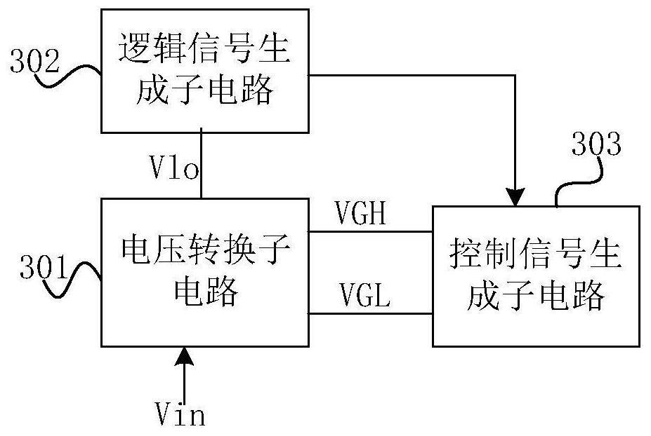
[0047] According to a specific implementation manner, the control signal generation circuit may include a voltage conversion subcircuit, a logic signal generation subcircuit and a control signal generation subcircuit, wherein,

[0048] The voltage conversion subcircuit is used to boost the input voltage to obtain the maximum on-state voltage and the minimum off-state voltage, and transmit the maximum on-state voltage and the minimum off-state voltage to the control signal generator The circuit is also used to step down the input voltage to obtain a logic voltage, and transmit the logic voltage to the logic signal generation sub-circuit;

[0049] The logic signal generating subcircuit is used to generate a logic signal according to the logic voltage;

[0050] The control signal generating subcircuit is used to generate the control signal according to the maximum on-state voltage and the minimum on-state voltage under the control of the logic signal.

[0051] Such as image 3 ...


PUM


Abstract

The invention provides a lighting test module. The lighting test module is used to perform a lighting test on the display panel. The lighting test module includes a data voltage generating circuit arranged on a peripheral circuit board; The preset data lines included in the display panel provide data voltages. In the lighting test module of the present invention, during the lighting test, the data voltage generation circuit that provides the data voltage is externally placed on the display panel and hardwareized, and the data voltage provided by the data voltage generation circuit for the preset data line , the number of preset data lines is flexible and variable, which is especially suitable for unconventional, low-resolution display panel development or process verification, and the process flow is simple when performing process verification on the display panel.

Description

technical field [0001] The invention relates to the field of display technology, in particular to a lighting test module. Background technique [0002] Liquid crystal glasses do not need color film, and the special panel (panel) of concave-convex lens is realized by controlling the liquid crystal inversion simulation. The number of data lines required by liquid crystal glasses is small, and the conventional source driver is used, which is limited in the binding size. The number of lines is wasted. At this stage, the process verification is mainly through a series of steps such as array substrate production, Cell (boxing), Cutting (cutting), Cell Test (boxing test), Bonding (binding), lighting, etc., and finally assembled into a display module group. The shortcomings of some display panels can be found in the box test stage. Whether the process is feasible needs to be bound to the Driver (Integrated Circuit) and the flexible circuit board. It can only be fully discovered aft...

Claims


Application Information

Patent Timeline
Patent Type & Authority Patents(China)
IPC IPC(8): G09G3/00
CPCG09G3/006
Inventor 王冬辉王泓赵伟利毕育欣陈小川赵文卿
Owner BOE TECH GRP CO LTD
Why Eureka
Try Eureka