
Array antennas and methods for improving their circular polarization performance

An array antenna and circular polarization technology, which is applied in the manufacture of antenna array devices, antennas, antenna arrays, etc., can solve the problem of narrow axial ratio bandwidth and standing wave bandwidth of single feed method, narrow antenna axial ratio bandwidth and standing wave bandwidth, complex structure, etc.

Inactive Publication Date: 2018-12-21
LEIHUA ELECTRONICS TECH RES INST AVIATION IND OF CHINA
View PDF10 Cites 5 Cited by
  • Summary
  • Abstract
  • Description
  • Claims
  • Application Information

AI Technical Summary

Problems solved by technology

In the prior art, there are single-feed method, multi-feed method and multi-element method to realize antenna circular polarization. Among them, the axial ratio bandwidth and standing wave bandwidth of the single-feed method are very narrow, and it is difficult to meet the requirements of wide frequency band; the multi-element method realizes Circularly polarized antennas often have relatively large antenna size and complex structure, which is not conducive to integration; the multi-feed method uses multiple feed points to feed the radiation patch of the antenna, and ensures the circular polarization performance of the antenna through the feed network, and The multi-feed method can overcome the problems of narrow antenna axial ratio bandwidth and standing wave bandwidth
However, through the research and design of circularly polarized antenna arrays by the multi-feed method, the usual method is to establish a model of a unit antenna, based on which the simulation design is carried out under periodic boundary conditions. The circular polarization of the array antenna designed by this method performance is not optimal

Method used


Image

  • Array antennas and methods for improving their circular polarization performance
  • Array antennas and methods for improving their circular polarization performance
  • Array antennas and methods for improving their circular polarization performance

Examples


Embodiment Construction

[0025] In order to make the objectives, technical solutions and advantages of the present invention clearer, the technical solutions in the embodiments of the present invention will be described in more detail below in conjunction with the drawings in the embodiments of the present invention. In the drawings, the same or similar reference numerals denote the same or similar elements or elements having the same or similar functions throughout. The described embodiments are some, but not all, embodiments of the invention. The embodiments described below by referring to the figures are exemplary and are intended to explain the present invention and should not be construed as limiting the present invention. Based on the embodiments of the present invention, all other embodiments obtained by persons of ordinary skill in the art without creative efforts fall within the protection scope of the present invention. Embodiments of the present invention will be described in detail below ...


PUM


Abstract

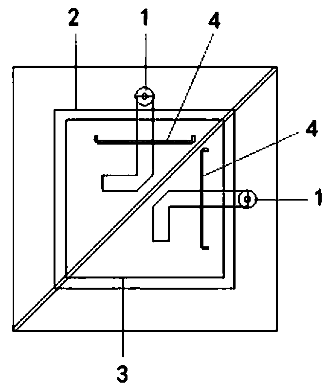
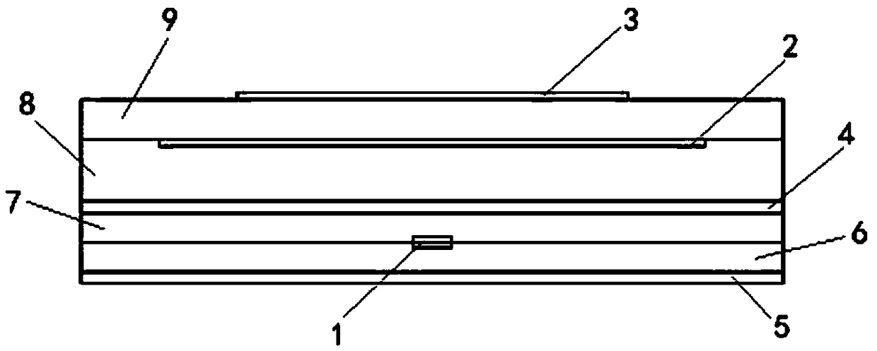
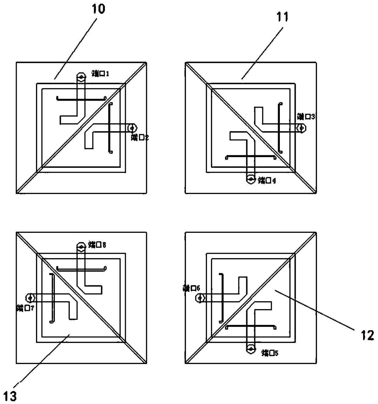
The invention discloses an array antenna and a method for improving the circular polarization performance thereof, the array antenna comprises a first unit, a second unit, a third unit and a fourth unit distributed in a rectangular array, wherein the first unit, the second unit, The third unit and the fourth unit have the same structure, and the first unit, the second unit, the third unit and thefourth unit are provided with feeding striplines, wherein the second unit is deflected by 90 degrees with respect to the first unit, the third unit is deflected by 180 degrees with respect to the first unit, and the fourth unit is deflected by 270 degrees with respect to the first unit. By changing the structure of the array antenna unit and then rotating the antenna element regularly, the instantaneous components of the instantaneous electric field vector of the array antenna element on the x-axis and y-axis in the two-dimensional coordinate system are nearly equal, so that the circularly polarized trajectory of the array antenna electromagnetic wave is nearly circular, and the circularly polarized performance of the array antenna is further improved.

Description

technical field [0001] The invention belongs to the technical field of antennas, and in particular relates to an array antenna and a method for improving circular polarization performance thereof. Background technique [0002] With the development of space and communication technology, circularly polarized antennas play an important role in the wireless field due to their great advantages. Antenna circular polarization means that the trajectory of the instantaneous electric field vector of the electromagnetic wave radiated by the antenna is circular or elliptical. In the prior art, there are single-feed method, multi-feed method and multi-element method to realize antenna circular polarization. Among them, the axial ratio bandwidth and standing wave bandwidth of the single-feed method are very narrow, and it is difficult to meet the requirements of wide frequency band; the multi-element method realizes Circularly polarized antennas often have relatively large antenna size a...

Claims


Application Information

Patent Timeline
IPC IPC(8): H01Q1/38H01Q1/48H01Q1/50H01Q21/00H01Q21/06H01Q15/24
CPCH01Q1/38H01Q1/48H01Q1/50H01Q15/24H01Q21/0075H01Q21/0087H01Q21/06
Inventor 田春胜史冰芸柯腾龙
Owner LEIHUA ELECTRONICS TECH RES INST AVIATION IND OF CHINA
Learn More